Reznor B Unit Installation Manual User Manual
Page 37
Form I-F/B, P/N 98126 R21, Page 37
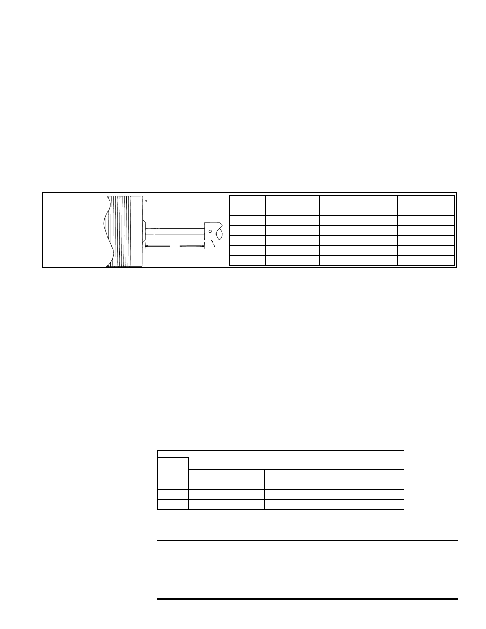
FIGURE 47 -
Proper
Position
of the Fan
Blade on the
Motor Shaft
Fan Motor
A
Fan
Hub
Model Size Electrical Supply Set Screw Torque In-Lbs "A" Hub to Motor
25
60 Hz
80 + or - 10
1-1/4" (32mm)
50
60 Hz
80 + or - 10
3/8" (9.5mm)
75
60 Hz
80 + or - 10
1/8" (3.2mm)
25,50,75
50 Hz
80 + or - 10
3-1/4" (82.6mm)
100-125
50 or 60 Hz
120 + or - 10
2-1/2" (63.5mm)
165-400
50 or 60 Hz
150 + or - 10
2-1/2" (63.5mm)
1. If the heater is installed, turn off the gas and disconnect the electric power.
2. Remove the left outer side panel (left when facing the rear of the unit). Disconnect
the fan motor wires.
3. Depending on the date that the heater was manufactured, it will have either a
lower-half fan guard only, two-piece full fan guard, or a one-piece full fan guard. If the
unit has a two piece fan guard, remove the tension mounted upper half fan guard and
the four screws that hold the lower half. If the unit has a one-piece fan guard, remove
all of the screws that retain the fan guard. Remove the assembled parts (the fan
guard, the motor, and the fan blade).
4. Disassemble and replace whatever parts are needed and reassemble using
whatever part(s) are being replaced and the original parts. If the fan guard is being
replaced, it is
important that the same hardware be used for attaching the motor to
the fan guard as was used with the original guard. These screws are especially made
to cut through the coating on the fan guard to provide adequate grounding for the
motor.
Be sure the fan blade is in proper position on the shaft. Position the fan as shown in
FIGURE 47 according to the chart.
Position the assembly on the heater. Attach the fan guard at the center mounts.
(
IMPORTANT: If replacing the fan guard, use the screws that held the original fan
guard. These specially designed screws will cut through the coating on the fan guard
to provide a ground for the fan motor.)
Rotate the fan blade to check for adequate clearance. If adjustment is required,
loosen the mounting screws, re-position the fan guard, and tighten the screws.
Rotate the fan blade and re-check for adequate clearance. Repeat this procedure
until the assembly is positioned properly.
5. If necessary, drill the required upper and lower fan guard mounting holes. Attach
the fan guard at all upper and lower mounting points using either the screws removed
or field-installed sheetmetal screws.
6. Reconnect the fan motor wires and replace the outer side panel.
7. Restore power to the heater and turn on the gas. Light, following the instructions
on the lighting instruction plate. Check for proper operation.
10.2.8 Vent System
Check the vent system at least once a year. Inspection should include all joints, seams,
and the vent cap. Replace any defective parts.
10.2.9 Blocked Vent
Switch
The manual reset blocked vent switch is located on the front top of the drafthood. The
sensor is located near the relief opening of the drafthood.
Blocked Vent Switch
Model
Size
Single-Stage Gas Controls
Two-Stage Gas Controls
Temperature Setting
P/N
Temperature Setting
P/N
25
200°F
112751
N/A
N/A
50
225°F
112752
N/A
N/A
100-400
275°F
121275
225°F
112752
10.2.10 Fan, Limit, &
ECO Controls
If it is determined that the fan or limit controls or the ECO device needs replacing, use
only factory-authorized replacement parts that are designed for your heater. See loca-
tions in
FIGURE 48.
WARNING: An ECO circuit interruption is a major failure caused by
a malfunction of the primary safety controls or mis-wiring, and will
require correction of the cause of the failure and the replacement
of the fan and limit controls and wiring before the heater can be
returned to service. See Hazard Levels, page 2.
NOTE: ECO control is not
on any units manufactured
after 8/2008. All units with
match-lit pilot have an ECO
device. Units with spark
pilot manufactured prior to
8/99 have an ECO device.
Fan Models: Follow these
instructions for replacement
of the fan guard, fan motor
or fan blades.