Electrical supply and wiring (cont'd), 2 supply voltage and wiring (cont'd), 3 control wiring – Reznor B Unit Installation Manual User Manual
Page 24
Form I-F/B, P/N 98126 R21, Page 24
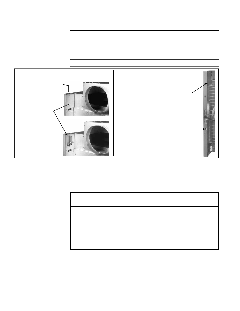
Threaded Hole
for Standard 1/2"
Electrical Fitting
Remove Access
Panel to Make
Connections
FIGURE 24 - Electrical Supply Connections
Note: Fan-type
heaters with optional
built-in disconnect
switch, have an
on/off switch located
near the electrical
supply access panel.
FIGURE 25 - Fan Model showing
location of Optional Unit-Mounted
Disconnect Switch and Reset Button
If equipped with unit-mounted
disconnect switch, on/off toggle
switch is near access panel to
electrical supply junction box.
Circuit breaker button for
Option AI-1 unit-mounted
disconnect switch
CAUTION: FAN-TYPE MODEL FOR
OPTIONAL 50 HERTZ OPERATION
A fan-type heater with Option AK11 is designed for operation from a
220-240V/50Hz/single phase power source. Connection to any other voltage
or frequency source may cause failure of the equipment and/or damage to
persons or property.
In the event that this product is purchased or destined for export markets, the buyer
is responsible for meeting any and all local codes covering installation and labeling
of the product. The equipment as provided by the manufacturer is design-certified
to ANSI Standard and comes with English-only labels and installation instructions.
7. Electrical
Supply and
Wiring (cont'd)
7.2 Supply Voltage and Wiring (cont'd)
and 25). This switch may be used to disconnect the power when servicing the heater
other than in the supply junction box.
WARNINGS: On a heater with a unit disconnect switch (Option
AI-1), when the power is turned off at the unit-mounted switch,
the supply lead in the electrical supply junction box (FIGURE 24)
remains energized. If service is to be done in the supply junction
box, turn off the power at the remote disconnect switch.
If you turn off the power supply, turn off the gas.
Specific wiring diagrams that include standard and factory-installed options are on with
the heater. Check the wiring diagram to identify optional equipment.
The operating sequence of the heater can be found on the heater wiring diagram and
is published in Paragraph 9, Check Installation and Start-Up.
Typical wiring diagrams
are FIGURES 30-33 showing single-stage heating with intermittent spark pilot.
7.3 Control Wiring
A thermostat is not standard equipment but is an installation requirement. Use either
an optional thermostat available with the heater or a field-supplied thermostat. Install
according to the thermostat manufacturer's instructions. Make sure that the heat antici-
pator setting on the thermostat is in accordance with the amperage value noted on the
wiring diagram of your heater.
Terminal Strip Connections - The standard heater is equipped with a two-screw ter-
minal connector strip (See
FIGURE 26) for easy connection to the low voltage controls
(24V).