Reznor B Unit Installation Manual User Manual
Page 35
Form I-F/B, P/N 98126 R21, Page 35
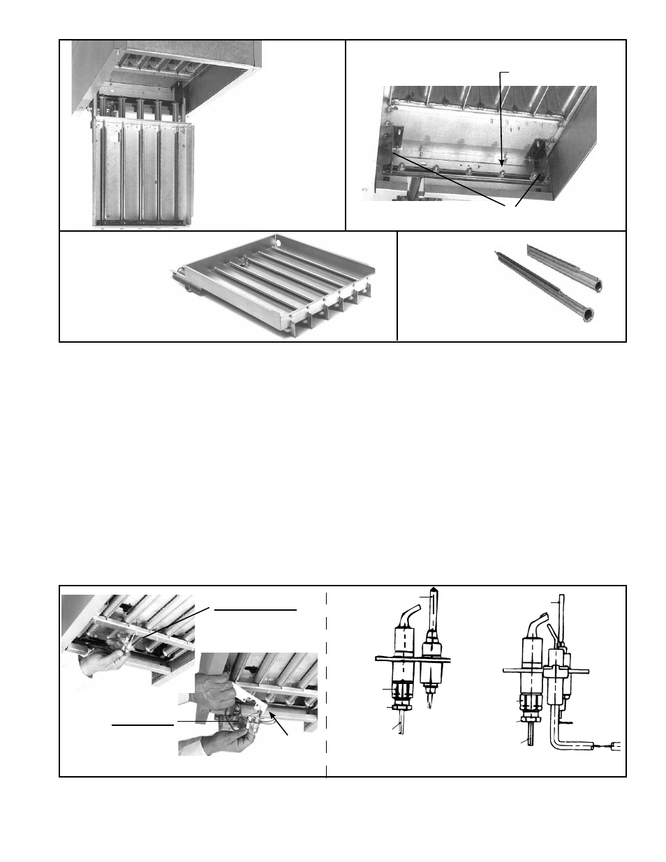
Burner Assembly Support Brackets
FIGURE 40 - Burner Orifices
Burner Orifices
FIGURE 42 -
Individual
Burners
FIGURE 41 - Burner
Rack Completely
Removed
Individual burners may be cleaned using air pressure. Use an air nozzle to blow
out scale and dust accumulation from the burner ports. Alternately, blow through
burner ports and venturi.
Use a fine wire to dislodge any stubborn particles. Do not use anything that might
change the port size.
d. To replace individual burners, reverse the above procedure.
10. To replace the burner rack assembly and the bottom panel, reverse the above
procedure (Steps 1-8).
When any service is completed, be careful to reassemble correctly to ensure that no
unsafe conditions are created. When re-lighting, always follow the lighting instructions
on the heater.
10.2.3 Pilot and
Ignition Systems
The pilot can be serviced by opening the bottom access panel of the heater. Follow the
first four steps of instructions for Burner Rack Removal, Paragraph 10.2.2. Remove the
pilot for maintenance or service, such as checking the wiring and cleaning the orifice.
In the event the pilot flame is short and/or yellow, check the pilot orifice for blockage
caused by lint or dust accumulation. Remove the pilot orifice and clean with air pres-
sure. Check and clean the aeration slot in the pilot burner.
Thermocouple
Orifice
Compression
Fitting
Pilot Tubing
Pilot Hole
Cover
Plate
Match-Lit Pilot
(on units mfgd
prior to 8/2008)
FIGURE 43 - Pilot
Removal
Spark Pilot
(be sure to re-install
Pilot Hole Cover
Plate)
Match-Lit Pilot
(units mfgd prior to 8/2008)
Spark Pilot
Orifice
Compression
Fitting
Pilot Tubing
Flame Rod
On a heater is equipped with a spark pilot, check the spark gap. Spark gap must be
maintained to .100". (See
FIGURE 44.) When re-installing the pilot of a heater with
optional spark ignition, be sure to include the pilot hole cover plate (See
FIGURE 43).
FIGURE 39 -
Burner Rack
Hinged Down