3 inlet air - blower model b, 3 vent control damper, option av7, 4 optional power venting - option ca – Reznor B Unit Installation Manual User Manual
Page 19
Form I-F/B, P/N 98126 R21, Page 19
6.2.3 Vent Control
Damper, Option AV7
The vent damper option is a motorized damper that
will close when the heater is not operating. The vent
damper is applicable only with spark ignition with
lockout (Control Option AH3). See
NOTES below
and follow the manufacturer's instructions to install it
in the vent. See the wiring diagram on the heater to
make the wiring connections.
NOTES: The wiring harness with the vent damper
is 8 ft (2.4M) in length. The vent damper should be
located as close to the heater as possible and cannot
FIGURE 17 - Option AV7,
Vent Control Damper
NOTE: A gravity-vented
unit heater manufactured
after August 7, 2008, MUST
be installed with either an
automatically controlled
motorized vent damper
(Option AV7) or power
venting (Option CA).
6.2.4 Optional Power
Venting - Option CA
Option CA is a motorized vent exhauster that is designed to permit the operation of
these gravity-vented heaters in areas of negative pressure up to 0.15" w.c. or where
horizontal venting is required.
NOTE: Do not install an
Option CA venter on a
heater equipped with
voltage option AK11,
220-240/1/50 Hertz.
The option package includes complete installation and wiring instructions. The venter
is wired so that when the thermostat calls for heat, the thermostat contacts close the
circuit which, after a delay of approximately 30 seconds, starts the venter. When the
venter starts, air from the venter blower closes an air flow switch that is built into the
venter. The closing of the air flow switch completes the electric circuit to the burner con-
trols, opening the gas valve. When the thermostat is satisfied, the thermostat closes
the gas valve and de-energizes the time delay relay. Approximately 45 seconds after
the thermostat is satisfied, the air flow switch resets to the open position.
The addition of the optional power venter changes the vent size requirements
of the heater. The vent sizes and allowable vent lengths are listed in the installation
instructions in the option package.
FIGURE 18 - Venter
Assembly and Adapter
The option package also includes
two hanger brackets to convert a fan-
type heater to four-point suspension.
Four-point suspension is required to
maintain the unit in a level position
without putting stress on the gas valve
or piping.
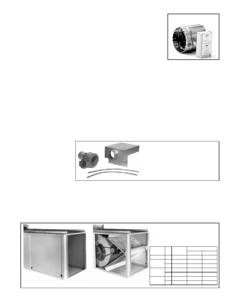
6.3 Inlet Air - Blower
Model B
FIGURE 19 - Optional
Field-Installed Blower/
Filter Cabinet
Blower Cabinet with Filters
(Option CW2 or CW3) -- side
panel removed to illustrate
interior of cabinet
Blower Cabinet
without filters (Option CW1)
6.3.1 Optional Blower/Filter Cabinet - Options CW1, CW2, or CW3
(Blower Models Only)
The blower/filter cabinet option is available for all Model B sizes. The blower/filter cabi-
net is shipped separately for field assembly and installation. The cabinet is adaptable
for use with either 1" or 2" filters and may be connected to a return air duct (includes
3/4" duct flange). Option CW1 does not include filters; CW2 includes 1" permanent
aluminum filters; and CW3 includes 2" permanent aluminum filters.
Follow the illustrated instructions included with the option package.
Model
Size
Qty
Filter
Size
Replacement P/N
1" Filter 2" Filter
25-125
1
20 x 20
101608
101621
165-200
1
16 x 25
101609
101622
1
20 x 25
101610
101623
250-300
2
16 x 20
101607
101620
2
20 x 20
101608
101621
400
2
16 x 25
101609
101622
2
20 x 25
101610
101623
be more than 8 ft (2.4M) from the ignition controller. The ignition controller has a safety
feature that once it is used with a vent damper, it will no longer operate a unit without
a vent damper.