Maintenance and service (cont'd), 2 maintenance procedures (cont'd) – Reznor B Unit Installation Manual User Manual
Page 36
Form I-F/B, P/N 98126 R21, Page 36
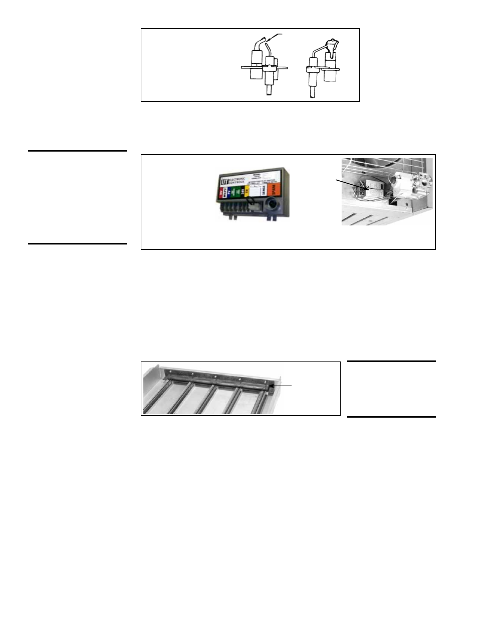
FIGURE 44 - Pilot
Burner Spark Gap
(Spark Pilot)
.100 spark gap
The
ignition controller of the optional intermittent electronic ignition pilot system is
visibly located on the back of the heater. (See
FIGURE 45.) Do not attempt to disas-
semble the ignition controller. There are no field replaceable components in the control
enclosure. However, each heating season the lead wires should be checked for insula-
tion deterioration and good connections.
FIGURE 45 - Ignition Controller,
UTEC 1003-514,
P/N 257010,
for Option AH3
Gas Control
Location
of Ignition
Controller
10.2.4 Burner Orifices
Heaters are shipped with orifices of proper size and type for gas and altitude specified
on the order. When ordering replacement orifices, give BTUH content, specific gravity
of gas, and altitude, as well as model and serial number of the heater.
Flash
Carryover
FIGURE 46 - Burner
Rack Flash Carryover
10.2.7 Fan or Blower
10.2.5 Flash
Carryover
See
FIGURE 46. The burner carryover system receives its gas supply from the main
burner ports. Check the carryover assembly and also the main burner ports for cleanli-
ness. Clean with air pressure.
CAUTION: Wearing
eye protection
when cleaning
this heater is
recommended.
10.2.6 Heat
Exchanger
Remove dirt and grease from the motor.
On fan model units, remove dirt and grease from the fan guard and blades. Use care
when cleaning the fan blades to prevent causing misalignment or imbalance. Check
that the hub of the fan blades is secure to the shaft.
On blower models,
remove the grease and dirt from the blower housing and check the
belt for wear and proper tension (See Paragraph 6.5).
Lubricate if the motor has oil cups or grease fittings. The motor supplied as standard
has lifetime lubrication and sleeve bearings.
On blower models, check current draw to motor rating plate.
The outside of the heat exchanger can be cleaned from the front of the heater with an
air hose and/or a brush. Remove all accumulated dust and grease deposits.
The inner surfaces of the heat exchanger can be reached for cleaning with the burner
rack removed. (See Paragraph 10.2.2.) Cleaning can be done with a long furnace
brush or a heavy wire to which steel wool has been attached. Brush up and down
inside each heat exchanger tube until all foreign material is removed. A flashlight is
helpful in examining the upper section of the tube.
Proper operation of the electronic spark ignition system requires a minimum
flame signal of .2 microamps as measured by a microampmeter.
10. Maintenance
and Service
(cont'd)
10.2 Maintenance
Procedures
(cont'd)
10.2.3 Pilot and
Ignition Systems
(cont'd)
CAUTION: Due to
high voltage on
pilot spark wire
and pilot electrode,
do not touch when
energized. See
Hazard Levels,
page 2.
Service NOTE: If replacing an earlier style of ignition controller, order replacement kit
P/N 257472 for a unit with recycling gas control Option AH2 or P/N 257473 for Option
AH3 gas control with lockout. (Option codes are listed on the unit wiring diagram.) Use
of a vent damper requires an ignition controller with lockout.