Clearances and dimensions (cont'd), 2 dimensions (cont'd), Figure 7 - model b dimensions - inches (mm) – Reznor B Unit Installation Manual User Manual
Page 10: Dimensions - inches
Form I-F/B, P/N 98126 R21, Page 10
B
A
Front View
13/16 (21)
Suspension Points (4)
- 3/8-16 female thread
(See Notes below)
A
K
Optional
Duct Flange
Horizontal
Vent Position
Vertical Vent
Position
H
N
P
R
S
2 (51)
T
E
Y
G
C
X
10
(254) Cabinet
Hanger
Location
2-1/4 (57)
Optional
Blower Cabinet
D
4-1/4 (108)
1/8 (3)
1-11/16 (43)
3/4 (19)
J
L = Gas Connection
(not gas supply line)
Electrical Supply
Connection
I = Vent Size
B/2
Z
W
K
13/16 (21)
M
3/4 (19)
F
U
Right Side View
Rear
View
Note
F
NoteG
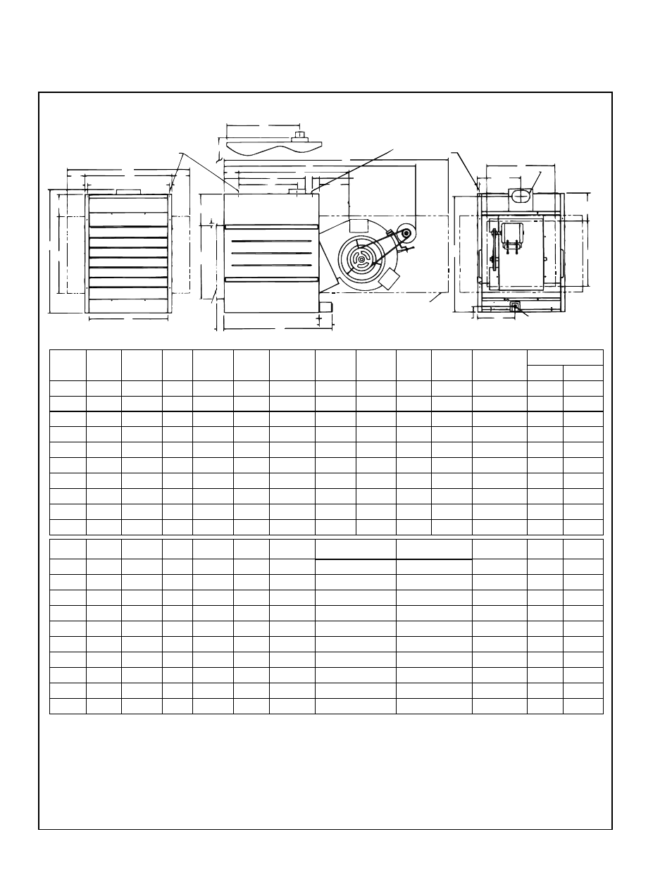
FIGURE 7 - Model B Dimensions - inches (mm)
Size
A
B
C
H
D
E
F
D
G
AC
H
I
J
K
AB
L
Hanger
Nat
Propane
25
30-5/32 13-9/16 43-3/8 31-7/16 5-27/32 14-7/16
61-3/8
19
4 Rnd 10-9/32
16
1/2
1/2
50
30-5/32 13-9/16
50
31-7/16 5-27/32 14-7/16
61-3/8
19
4 Rnd 10-9/32
16
1/2
1/2
75
30-5/32 15-9/16
50
31-7/16 5-27/32 14-7/16
61-3/8
19
5 Oval 10-17/32
16
1/2
1/2
100
30-5/32 17-9/16
50
31-7/16 5-27/32 14-7/16
61-3/8
19
6 Oval 12-29/32
16
1/2
1/2
125
32
23-5/16 47-1/2 31-7/16 5-27/32 14-7/16 65-29/32 17-15/16 7 Oval 14-7/16
16
1/2
1/2
165
40-5/32 20-5/16
61
35-15/16 4-7/8
19-15/32
76-1/8 23-13/32 8 Oval 14-9/32
24
1/2
1/2
200
40-5/32 23-5/16 66-1/2 35-15/16 4-7/8
19-15/32
76-1/8 23-13/32 8 Oval 14-13/32
24
1/2
1/2
250
43-9/16 28-13/16 66-1/2 35-15/16 4-7/8
19-15/32
76-1/8 21-13/16 10 Oval 12-11/32
24
1/2
1/2
300
43-9/16 28-13/16 66-1/2 35-15/16 4-7/8
19-15/32
76-1/8 21-13/16 10 Oval 12-11/32
24
3/4
1/2
400
43-9/16 37-1/16 66-1/2 35-15/16 4-7/8
19-15/32
76-1/8 21-13/16 12 Oval
13
24
3/4
1/2
Size
M
A
N
A
P
A
R
A
S
B
T
B
U
A
W
A
X
E
Hanger
Y
Z
25
3-23/32 20-15/16 17-3/4
5-1/4
10-3/4
8-7/16
14-3/4
6-3/16
31-7/32
21-1/2 27-21/32
50
3-23/32 20-15/16 17-3/4
5-1/4
10-3/4
8-7/16
14-3/4
6-3/16
31-7/32
21-1/2 27-21/32
75
2-23/32 20-15/16 17-3/4
5-1/4
12-3/4
8-7/16
14-3/4
6-3/16
31-7/32
21-1/2 27-21/32
100
1-23/32 20-15/16 17-3/4
5-1/4
14-3/4
8-7/16
14-3/4
6-3/16
31-7/32
21-1/2 27-21/32
125
1-11/32 25-15/16 17-3/4
5-1/4
20-1/2
8-7/16
20-1/2
6-3/16
35-3/4
21-1/2
28-1/2
165
2-27/32 25-15/16 25-1/4
7-1/4
17-1/2
11-7/16
20-1/2
7-15/16
36-11/16
27
36-25/32
200
1-11/32 25-15/16 25-1/4
7-1/4
20-1/2
11-7/16
20-1/2
7-15/16
36-11/16
27
36-25/32
250
5-29/32 40-9/16 25-1/4
7-1/4
26
11-7/16
26
7-15/16
36-11/16
27
38-3/8
300
5-29/32 40-9/16 25-1/4
7-1/4
26
11-7/16
26
7-15/16
36-11/16
27
38-3/8
400
6-25/32 50-9/16 25-1/4
7-1/4
34-1/4
11-7/16
34-1/4
7-15/16
36-11/16
27
38-3/8
Dimensions - inches
NOTES:
A
When equipped with optional blower cabinet.
B
When equipped with optional duct flange.
C
Dimension includes a 3/4" flange on the rear of the blower cabinet.
D
Use with 4-point suspension without blower cabinet. If installing hanger kit Option CK19, suspension points change; see Paragraph 5.2.1.
E
Use with 4-point suspension with blower cabinet.
F
Contactor is standard on Models 300 and 400; optional on other sizes.
G
Contactor location with optional three phase motors on Sizes 50, 75, 100 and 125.
H
Deduct 6-5/8" (168mm) on Sizes 50, 75, and 100 when equipped with direct drive motor.
4. Clearances and Dimensions (cont'd)
4.2 Dimensions (cont'd)