B13 - testing the condensate trap level switch, B14 - removing and replacing the condensate trap, Testing the condensate trap level switch – LAARS NeoTherm NTV (Sizes 150–285 MBTU/h) - Service Manual User Manual
Page 41: Removing and replacing the condensate trap, B13 b14
31
Service Manual NeoTherm 80 - NeoTherm 285
Testing the Condensate Trap Level Switch
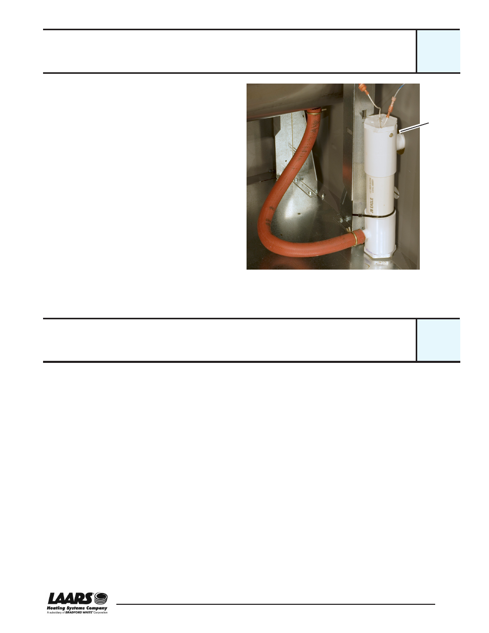
Fig. B13-1 - Small condensate trap assembly (typical)
Some operating conditions can cause small particles
of mineral material to be formed in the heat exchang-
er and collect in the condensate trap. The drain can
also be blocked if it is frozen or plugged with debris.
If the water cannot drain freely, it can back up into
the heat exchanger. The level switch is designed to
prevent this by shutting off the unit before the water
can reach the heat exchanger.
This assembly uses a float-type switch. To test, plug
the outlet (the higher fitting on the assembly). Mea-
sure the resistance across the switch contacts when
the assembly is empty. At this point, the contacts
should be closed (no resistance). Next, add water at
the inlet (the lower fitting). As the water level rises in-
side the assembly, you should see the contacts open
(infinite resistance).
Removing and Replacing the Condensate Trap
The NeoTherm unit is designed to operate in the “condensing” mode.
The combustion of natural gas produces a lot of water vapor. In the NT
unit, this water vapor is condensed out of the exhaust gas inside the heat
exchanger. The water is collected from the bottom of the heat exchang-
er, and sent to the condensate trap. The trap includes a float valve. If
the condensate drain is plugged or blocked for some reason, the float
rises inside the trap. If the water rises high enough, the float trips a
switch and prevents the NT unit from firing. This means the condensate
water can never back up into the heat exchanger.
Note that the condensate water can be hot. The water is also acidic, and
can damage metal pipes.
The photo above shows a condensate trap from a smaller NT unit. The
water enters through the hose at the bottom of the unit, and exits through
the top. At the top of the unit you can see the two wires for the float
switch.
The cap on the PVC assembly is held in place by a set-screw. Once you
remove this screw, you can remove the cap and unscrew the switch.
Set-
screw
B13
B14