Great Planes ESP6 Easy Sport 60 - GPMA0152 User Manual
Page 45
D 3 On the Easy Sport 40, glue the servo tray and the
die-cut 1/8" ply servo tray support (STS) securely in
place with medium or thick CA Add thick CA along the
joints to lock the tray in place
On the Easy Sport 60, do not glue the servo tray in
place at this time After the plane is covered and the
accessories are installed, the servo tray can be moved
forward or aft to adjust the balance point.
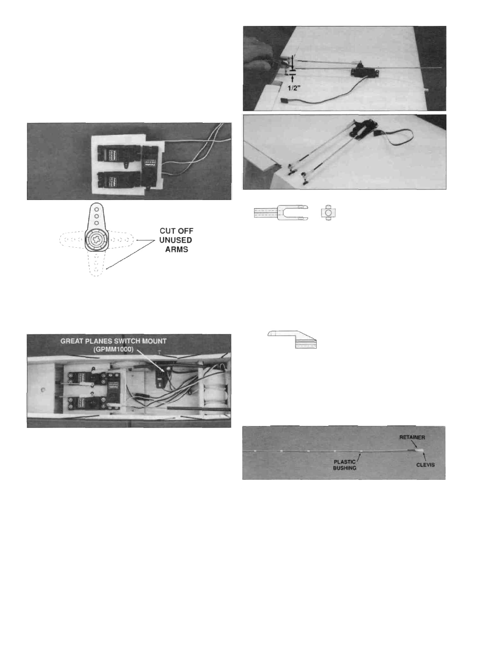
D 4 Mount the servos to the tray with the screws
included with your radio Attach the servo arms to the
servos with the hardware supplied with the radio You
may trim the servo arms to the shape required by the
particular application (study the photos)
D 5 Install the switch on the side opposite the engine
exhaust We added a Great Planes Switch Mount &
Charge Jack (GPMM1000) for convenience and ease of
use at the field Hook up the receiver and receiver
battery following the manufacturer's instructions Wrap
the receiver battery and receiver in 1/4" foam rubber,
then temporarily secure them in the fuselage After the
model has been balanced, use "popsicle sticks" or
leftover balsa glued between the fuse sides to
permanently hold the components in place Note The
compartment directly under the fuel tank has been
designed to house the battery in the event that nose
weight is needed for balancing Instead of adding weight
in the form of lead, try moving the battery to this location
during balancing.
Swivel Clevis & Swivel
D 6 Install the aileron servo as shown in the photo Make
sure the servo horn is toward the trailing edge Assemble
the swivel clevises then thread a 12" wire pushrod at least
13 revolutions onto each of them Thread the swivels onto
the torque rods until they are 1/2" (1/4" on the Easy Sport
60) above the trailing edge Cut off the excess threaded
torque rod wire or it may hit the wing mount plate when
the wing is mounted on the fuse.
Faslink™ Pushrod Keeper
D 7. Center the ailerons, then mark the pushrods at the
point where they meet the holes in the servo arm Make
a 90 degree bend in the wires Enlarge the servo horn
holes with a 5/64" drill bit Insert the bent wire pushrods
into the servo horn Then secure them with Faslink™
pushrod keepers and cut off the excess rod
D 8 Cut ten 3/16" bushings from the supplied 6-1/2"
inner plastic pushrod Slide five bushings onto two 36"
pushrods that are threaded at one end, spreading them
out as shown on the plan If the bushings are tight and
difficult to slide on, cut them to a shorter length Check
the fit on both pushrods making sure that the bushings
won't come out of the outer tube during operation If they
do, they could snag on the outer tube thereby
preventing control movement If needed, a small drop of
thin CA will hold the bushings in position.
45