Great Planes ESP6 Easy Sport 60 - GPMA0152 User Manual
Page 43
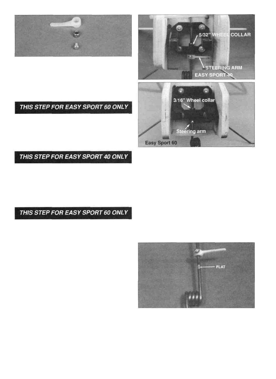
D 7. On the Easy Sport 40, align the threaded hole in
one 5/32" wheel collar with the small hole in the side of
the nylon steering arm. Keeping this alignment, press
the wheel collar into the nylon steering arm. On both the
Easy Sport 40 and 60, thread the 6-32 x 3/16" machine
screw into the steering arm assembly.
D 8. On the Easy Sport 60, remove the fuel tank hatch
and insert a 3/16" drill bit through the holes for the nose
gear. Twist the drill bit a couple of times to mark the hole
location on the bottom sheeting. Use a hobby knife to
cut a small hole at the mark. Then, enlarge the hole to
3/8" in the bottom sheeting.
D 9. On the Easy Sport 40, slide the steering arm onto
the nosegear wire above the coil. Slide the nose gear
wire through the bottom hole in the engine mount. The
other 5/32" wheel collar and the 6-32 hex head set
screw are used in the center opening of the engine
mount (above the steering arm) to retain the nose gear
as shown in step 13.
D 12. When everything is aligned and the model is
sitting correctly, tighten the 6-32 x 3/16" machine screw
on the steering arm tight enough to leave a mark on the
nosegear wire. Remove the nosegear from the engine
mount and remove the steering arm assembly.
D 10. On the Easy Sport 60, slide the nosegear wire
through the bottom sheeting. Then, slide the steering
arm on the nosegear wire between the bottom sheeting
and the engine mount. The 3/16" wheel collar and the 6-
32 hex head set screw are used in the center opening of
the engine mount (above the steering arm) to retain the
nose gear as shown in step 13.
D 11. On both the Easy Sport 40 and 60, position the
model upright on its landing gear and adjust the
nosegear wire (by sliding the steering arm and wheel
collar up or down) until the model sits level or slightly
nose down. Note: The steering arm needs to be rotated
away (approximately 1/2") from the firewall when the
axle is aligned for straight ahead steering. This allows
the steering pushrod to pull the steering arm far enough
for effective steering. For reference, also see the photo
at step 13.
D 13. The reason for marking the nosegear wire in the
previous step is so you can locate the spot for a "flat"
that will need to be filed into the wire. The procedure for
making the flat is described in the next column.
43