Futaba 14MZ User Manual
Page 43
Confi rm that the rate of the slowest position (0%) of
the stick is 0% (initial setting).
Be sure that when set to high side 100%, the curve
of any condition does not exceed 100%.
Example of pitch curve setting:
1. Call the pitch curve of each condition with
the condition select switch.
*Pitch curve graph display can be switched to pitch angle
direct reading display.
A. Pitch curve (Normal)
Make the pitch at hovering approximately +5º~6º.
Set the pitch at hovering with the stick position at
the 50% point as the standard.
*Stability at hovering may be connected to the throttle curve.
Adjustment is easy by using the hovering throttle function
and hovering pitch function together.
B. Pitch curve (Idle up 1)
The idle up 1 pitch curve function creates a curve
matched to airborne fl ight.
Set to -7º~+12º as standard.
C. Pitch curve (Idle up 2)
The high side pitch setting is less than idle up 1.
The standard is +8º.
D. Pitch curve (Hold)
At auto rotation, use the maximum pitch at both
the high and low sides.
[Pitch angle setting example]
Throttle hold: -7º~+12º
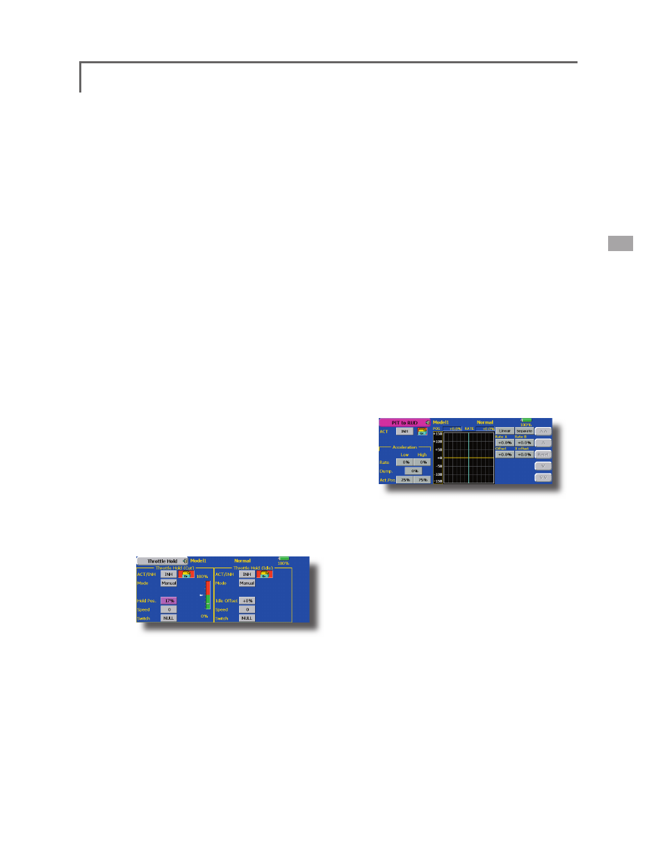
6. Throttle hold setting
Call the Throttle Hold function from the Model
Menu and switch to the throttle hold condition with
the condition select switch.
Note: At initial setting, the setting mode is the
group mode. Since this function is not used at other
conditions, switch to the single mode before setting.
●Setting to the state which activates the
function
The throttle hold function allows setting for throttle
cut and switching of the function fi xed at the idle
position by switch for training. Either one or both
functions can be performed.
●Hold position setting
This function sets the servo operation position at
throttle hold. (Throttle cut and idle positions)
●Other settings
When you want to link operation with stick
manipulation, the Auto mode can be set.
When you want to adjust the servo speed, adjust
[Speed].
7. Pitch to RUD mixing setting
Use this function when you want to suppress
the torque generated by the changes in the pitch
and speed of the main rotor during pitch operation.
Adjust it so that the nose does not swing in the
rudder direction. However, when using a heading
hold gyro like those shown below, do not use Pitch
to RUD mixing.
Note: When using a GY601, GY502, GY401, or other
heading hold gyro, this Pitch to RUD mixing should
not be used. The reaction torque is corrected at
the gyro side. When operating the gyro in the AVCS
mode, the mixed signal will cause neutral deviation
symptoms and the gyro will not operate normally.
Call the Pitch to RUD mixing function from the
Model Menu, and set the curve for each condition.
(At initial setting, this function is in the "INH"
state. To use it, set it to the "ON" state.)
(17 points curve)
Curve setting of up to 17 points is possible.
However, in the following setting example, a
simple curve can be adjusted by using the [Linear]
curve type.
Note: At initial setting, the setting mode is the group
mode. In this mode, the same contents are set at in
all conditions. When you want to set the selected
condition only, switch to the single mode.
Call the mixing curve of each condition with the
condition select switch.
●Throttle hold curve adjustment
The throttle hold curve is used when performing
auto rotation dives.
43