FingerTec AC800 Plus MC User Manual
Page 34
35
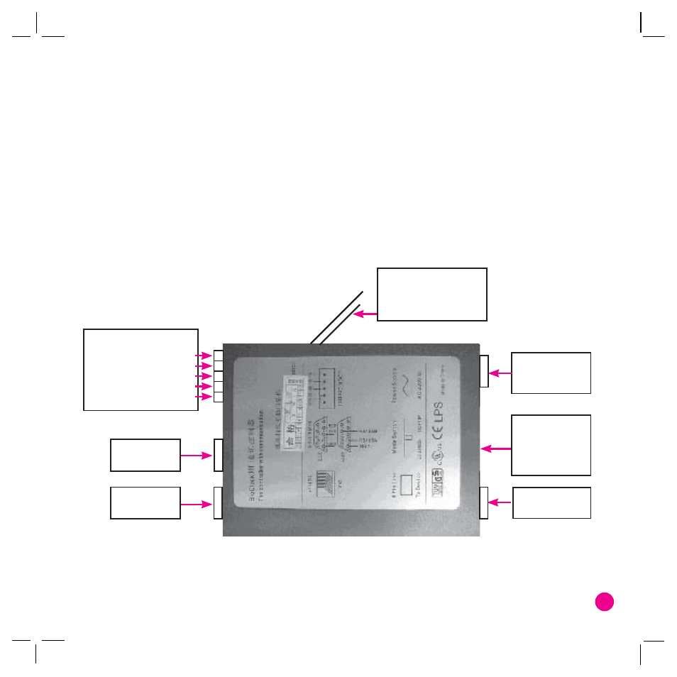
Additional DC input
White => GND
Blue/white => +12v
NO => door lock +
COM => Door lock-
NC => N/A
Power supply
PUSH => push button
220 V
GND => push button
Comm.
Selector
RS232/485
232/485 or
TCP-IP
TCP/IP
To reader
4
Power Supply:
Plug in the power cable provided here for supply of electricity to the reader.
5
Lock Control:
This port allows you to connect to an optional electromagnetic door (EM lock)
and door push button.
6
Serial Port:
RS232 is a serial communication cable used to connect from this port at one
end to a serial port of a PC at another end. RS485 cable extender should be connected to
this port and the other end should connect to an optional RS232/RS485 Data Converter
before it can be connected to the serial port of a PC.
7
TCP/IP Port:
A straight RJ45 cable is used to connect to a network switch/hub. A crosso-
ver RJ45 cable is used instead to connect directly to a PC network port.
The diagram of an I/O Controller and its points of connections.