Installation & communications 34-44, For fingertec installer), Connections available – FingerTec AC800 Plus MC User Manual
Page 33: Startup and shutdown, Communication connection door lock connection
34
Note
This Chapter is meant for qualified installer only.
The installation of FingerTec® reader shall be han-
dled by a well-trained installer. If you are not a quali-
fied installer, you can ignore this Chapter or this
Chapter serves as reference for all types of connec-
tions available for the FingerTec® reader only.
FOR AC800 SERIES
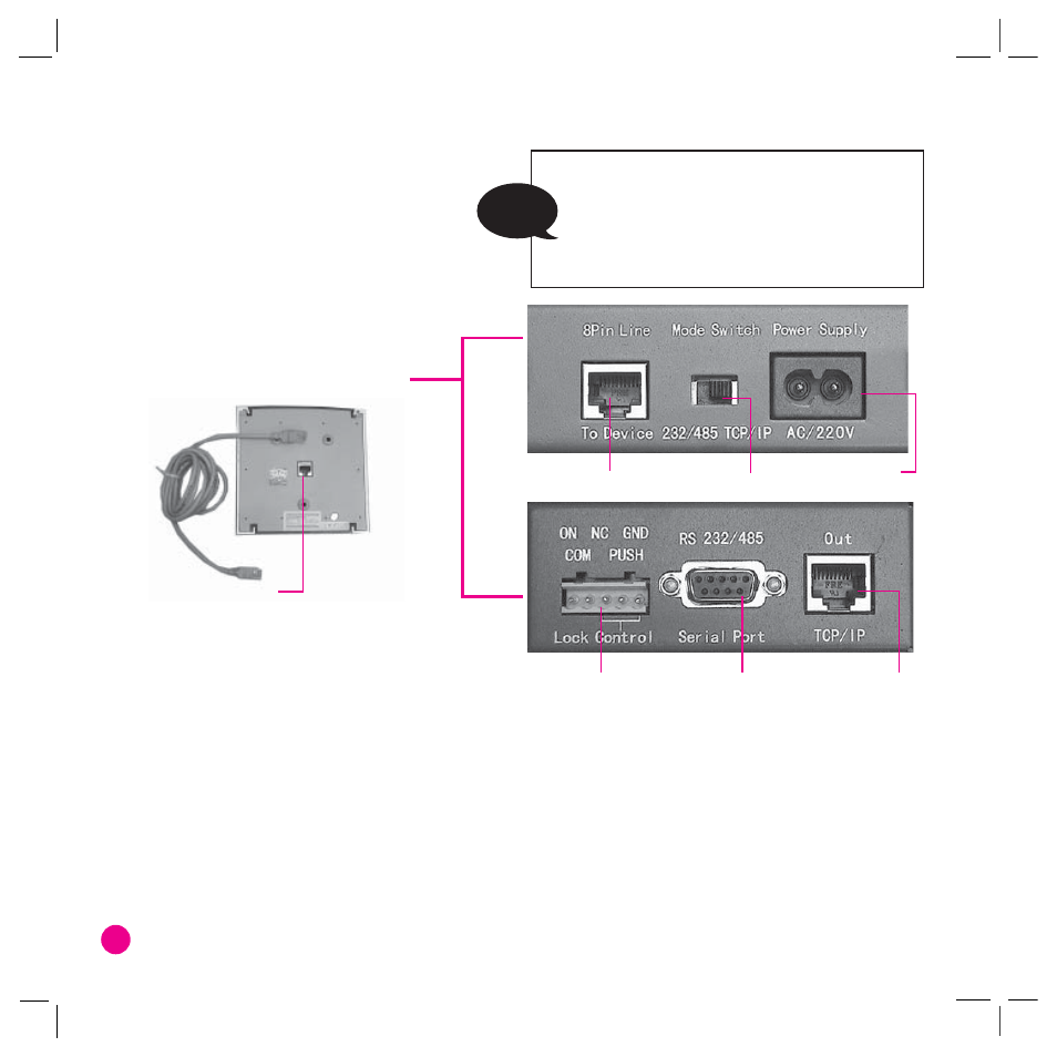
The Communication I/O Controller
•
2 8 Pin Line Port
•
3 Mode Switch
•
4 Power Supply
•
1 Data I/O Port
•
5 Lock Control
•
6 Serial Port
•
7TCP/IP Port
•
5
•
INSTALLATION & COMMUNICATIONS
CONNECTIONS AVAILABLE
1
Data I/O Port:
The port is located at the back of the reader. This port is connected to the
8-Pin Line port at the Communication I/O Controller.
2
8-Pin Line Port:
Located at the back of the Communication I/O Controller. This port con-
nects to the back of the reader using the straight RJ45 cable provided. The distance from the
controller to the reader is recommended to be not more than 15 meters.
3
Mode Switch:
This switch switches between 2 different communication types. The switch on
the left is for RS232/RS485 connection and the switch on the right, is for TCP/IP connec-
tion.