2 expansion interface, 3 expansion cables, Expansion interface – Toshiba SX 2000 User Manual
Page 70: Expansion cables
Attention! The text in this document has been recognized automatically. To view the original document, you can use the "Original mode".
1.5 Units
1.5.2
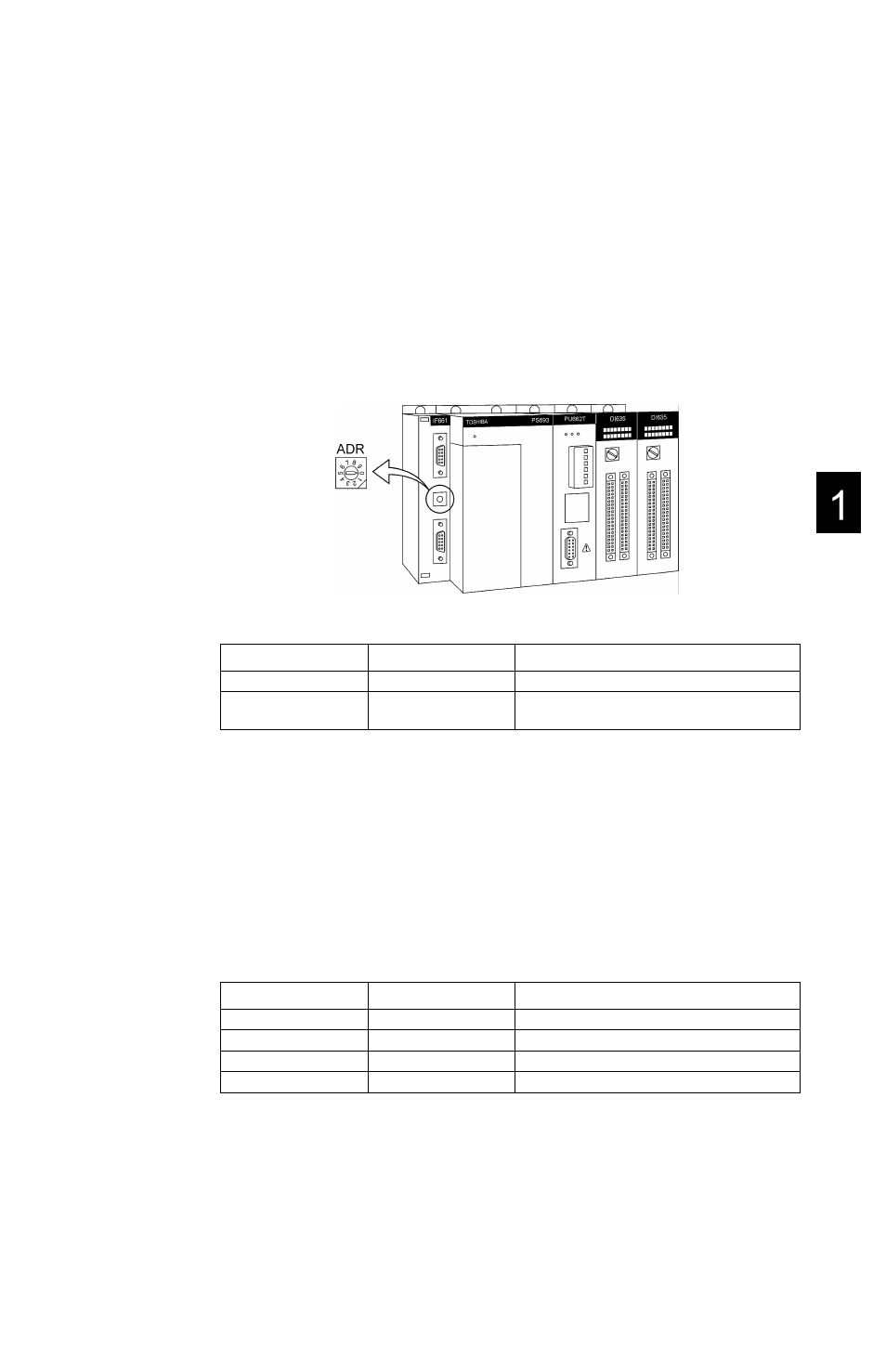
Expansion interface
The expansion interface IF661 is mounted on the left side slot of base to expand
bases after removing the unit cover. Set the unit No. (called unit address) before
operating. The unit address is set by a rotary switch in the middle of the expansion
interface removed the cover.
Setting the unit No.
The rotary switch to set unit address is provided between two expansion connectors.
The upper side connector is for input from previous unit and the lower side connector
is for output to the next unit.
Mounted on
Switch setting
Remarks
Basic unit
0
Expansion unit
1,2,3
Set in order to 1>2>3, starting from the unit
closest to the basic unit.
NOTE
i)
Switches will be set to 0 at the factory.
ii) Be careful not to duplicate unit Nos. on units.
iii) Do not use setting 4 - 9, as these are not for use.
1.5.3
Expansion cables
These are used for connecting the basic unit and the expansion units.
They are available in the following four lengths.
Type
Length
Remarks
CS6R3
30cm
CS6R5
50cm
CS6R7
70cm
CS6*1
1.2m
NOTE
The maximum cable length between units is 1.2m.
The maximum total cable length is 3.6m.
6F8C0926
53