Data format – Toshiba SX 2000 User Manual
Page 102
Attention! The text in this document has been recognized automatically. To view the original document, you can use the "Original mode".
2.3 I/O Module Specification
Data format
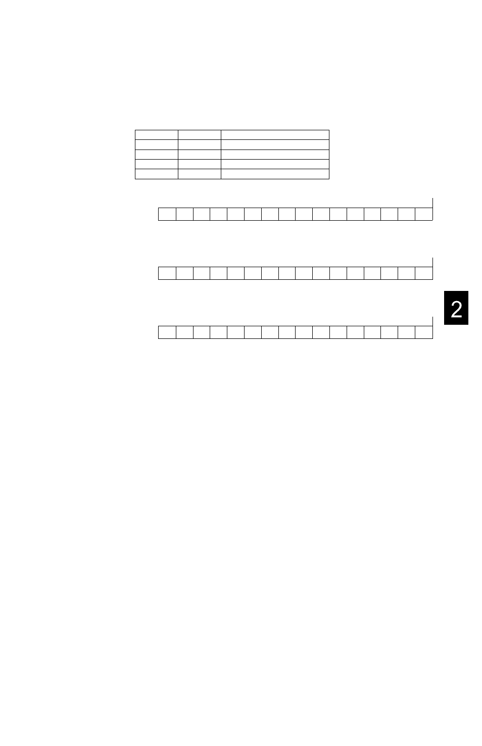
(1) Basic registers
Change detection status and Input data
S2T
S2
Description
XWn
%IWn
Rising edge detection status
XWn+1
%IWn+1
Falling edge detection status
XWn+2
%IWn+2
Input data
XWn+3
%IWn+3
No use (reserved)
[Rising edge detection status bit assignment;
Bit
F
E
D
C
B
A
9
8
7
6
5
4
3
2
1
0
US
US
US
US
US
US
US
US
US
US
US
US
US
US
US
US
US: When corresponding bit of input data changes from OFF to ON, it sets to ’1
[Falling edge detection status bit assignment]
Bit
LS: When corresponding bit of input data changes from ON to OFF, it sets to ’1
[Input data bit assignment]]
Bit
F
E
D
C
B
A
9
8
7
6
5
4
3
2
1
0
LS
LS
LS
LS
LS
LS
LS
LS
LS
LS
LS
LS
LS
LS
LS
LS
F
E
D
C
B
A
9
8
7
6
5
4
3
2
1
0
F
E
D
C
B
A
9
8
7
6
5
4
3
2
1
0
This register reflects the current input signal status.
When the interrupt enable flag is set to ON (DE=’T) and the rising edge detection is selected
(UE=’T), the CD633 sets corresponding bit of the change detection status register (US) and
generates interrupt to the controller at the time of input signal change from OFF to ON.
As same manner, when the falling edge detection is selected (LE=’T), the CD633 generates
interrupt at the time of input signal change from ON to OFF.
If both UE and LE are set’T, the interrupt is generated at the time of both change from OFF
to ON and from ON to OF
The change detection status is cleared to ’O’, when the controller is read the change
detection status and input data. Therefore make the application program to read the change
detection status and input data (3 words) at the same time by the direct I/O instruction, in the
I/O interrupt program.
6F8C0926
85