7 i/o wiring, I/o wiring, J j ililt – Toshiba SX 2000 User Manual
Page 156: J j l lilt, J j j, I—i—i—i, I i i i
Attention! The text in this document has been recognized automatically. To view the original document, you can use the "Original mode".
4.7 I/O wiring
4.7 I/O wiring
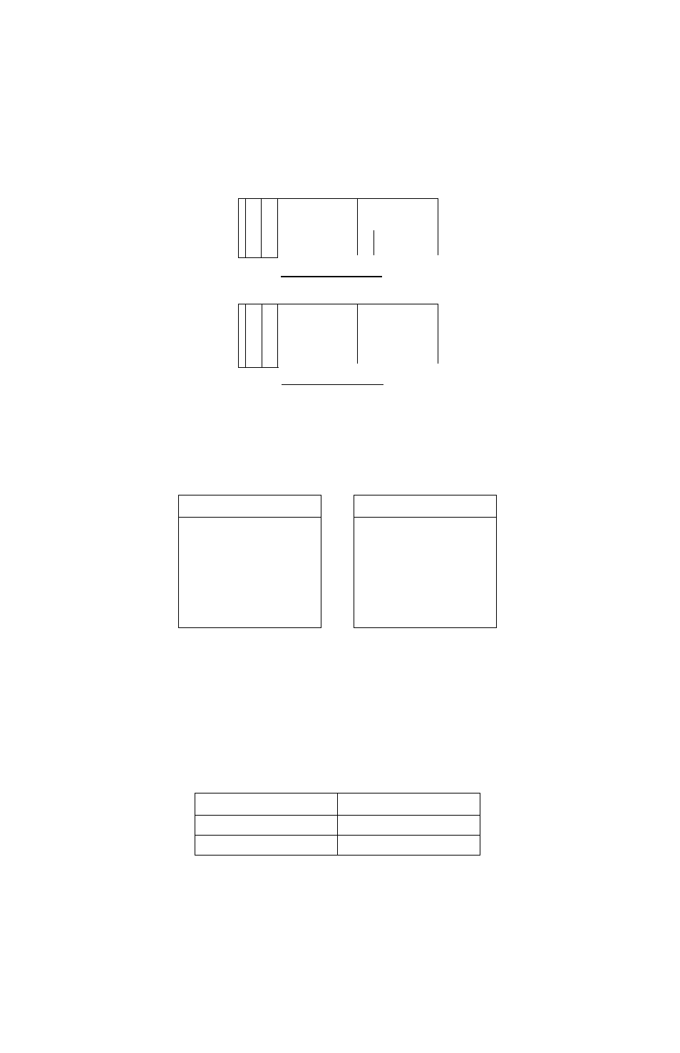
Pay attention to the following points when mounting and wiring the I/O modules.
Basic unit
Low-power
signal duct
Q.
Q.
3
yj
O'
5
o
Q.
c
I I I I
II II
p
u
Low-power
High-power
T
i
system I/O
I I I I
system I/O
I I
J J J
J J ILILT
Expansion unit
T
—I—I—I—I—
—I—I—I—I—
I
•
Q.
Q.
3
yj
O'
5
o
Q.
I I I I
Low-power
I I I I
High-power
system I/O
I I I I
system I/O
I I I I
J J J
J J L LILT
70mm or more
200mm or more
◄------------------------------►
High-power
signal duct
Power line
Low-power system I/O
High-power system I/O
DC input module
AC input module
Analog input module
DC output module
Analog output module
AC output module
Pulse input module
Positioning control module
Serial Interface
Transmission module
Relay output module
B
(1)
To improve the unit’s resistance to signal interference, install modules for low-
voltage signals toward the left of the unit, and modules for power signals toward
the right. Also, separate the wires of each.
(2)
Allow at least 70mm clearance between the units and between other control
equipment to allow access for maintenance and ventilation.
(3)
When installing the unit near high-voltage or high-power equipment, leave at
least 200mm clearance, or shield the unit with a steel plate.
(4) Refer to the following table for the size of I/O cables.
Type of module
Cable size
16-point module
0.5~1.25mm^
32/64-point module
0.1~0.3mm2
However, for common lines, use a thicker size which takes account of the
current capacity. Also, for cables outside the panel, the use of cable of at least
1.25mm^ is recommended to keep the impedance low.
6F8C0926
139