Toshiba SX 2000 User Manual
Page 131
Attention! The text in this document has been recognized automatically. To view the original document, you can use the "Original mode".
Chapt.3 Precautions for I/O Modules
(
8
)
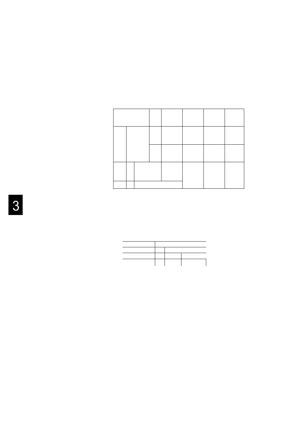
If dynamic scan input is configured using a DC input module and a DC
output module, in addition to the response-delay of output and input,
consider the difference of timing caused by the S2T scan. Moreover, diodes
must be installed to prevent erroneous input caused by detour circuit, (the
figure below is an example of 4x4 input)
Input module
Dl
DO
COM
Output module
1
2
3
6 1 a
o 1 e
“V
r+*5
6 irn
COM
P24
0
¿|_b
¿(.j
6 |_n
i
|_C
^ |_g
ilk
6 1 0
1
2
3
ii_d
4 i_h
i ( _ l
b|_p
hh
J
For example, when contact a is ON, the change timing between output 0
and input 0 is as follows.
S2T scan cycle
Output 0 (internal)
Output 0 (external)
Input 0 (internal)
Input 0 (external)
J2L
£
wmm
M
mm
,
1
*
^
T
2
^
T,:Output response delay
T
2
:lnput response delay
Note that the change timing of output 0 and input 0 will be affected with the
scan time of the S2T and the response time of input and output.
1 1 4
Sequence Controller S2T