Figure 3-11, Cabletron systems of – Cabletron Systems 2E43-51R User Manual
Page 39
Connecting to the Network
2E43-51/2E43-51R User’s Guide
3-15
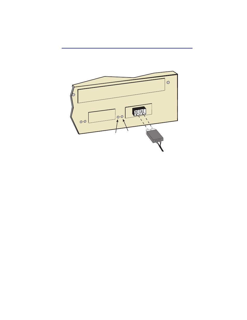
3.
At the other end of the fiber optic cable, attach the SC connector to the
other device.
Figure 3-11
FE-100FX and FE-100F3 Ports
4.
Verify that a Link exists by checking that the port RX LED is on
(flashing amber, blinking green, or solid green). If the RX LED is off
and the TX LED is not blinking amber, perform the following steps
until the RX LED is on:
a.
Check that the power is turned on for the device at the other end of
the Link.
b.
Verify proper crossover of fiber strands between the applicable
port on the 2E43-51 and the fiber optic device at the other end of
the fiber optic link segment.
c.
Verify that the fiber connection meets the dB loss specifications
outlined in
If a Link has not been established, contact the Cabletron Systems Global
Call Center. Refer to
2251-34
RX LED
TX LED
6
5