7 waterside inspection, Innovation series water heaters gf-128 – AERCO Innovation (G-10-1350 to G-11-0563) User Manual
Page 65
Chapter 6
Innovation Series Water Heaters
GF-128
Maintenance
USER MANUAL
OMM-0079_0B
07/21/11 AERCO International, Inc.
· 100 Oritani Dr. · Blauvelt, NY 10913 · Ph: 800-526-0288
Page 65 of 200
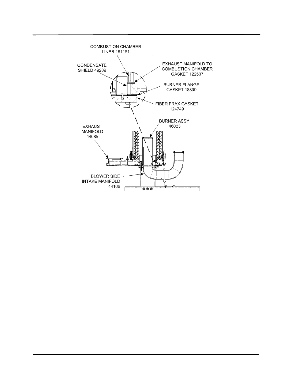
Figure 6-6. Combustion Chamber Liner & Gasket Locations
IMPORTANT
Prior to reassembly, ensure that the combustion chamber liner is installed prior to
reinstalling the exhaust manifold.
During reassembly, apply high-temperature, anti-seize lubricant to the threads of
the igniter-injector and grounding screw. Also, ensure that the igniter-injector and
staged ignition assembly are properly positioned and are not contacting other
components. Torque the igniter-injector to 15 ft-lbs.
19. Beginning with the exhaust manifold assembly removed in step 15, reinstall all the components in the
reverse order that they were removed.
6.7
WATERSIDE INSPECTION
The waterside of the heating surfaces may be inspected by removal of the top heater head. (See Figure 6-
6). Prior to performing the inspection, ensure that the following replacement gaskets are available:
GP-18556
Release Gasket
GP-18532
Shell Gasket
To inspect the waterside of the heat exchanger, proceed as follows: