Innovation series water heaters – AERCO Innovation (G-10-1350 to G-11-0563) User Manual
Page 18
GF
-
128
Innovation Series Water Heaters
Chapter 2
OMM-0079_0B
USER MANUAL
Installation
Page 18 of 200
AERCO International, Inc.
· 100 Oritani Dr. · Blauvelt, NY 10913 · Ph.: 800-526-0288
07/21/11
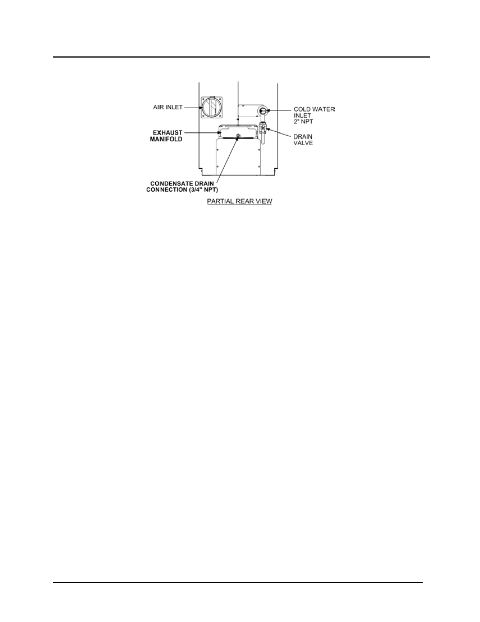
Figure 2-6. Condensate Drain Connection Location
A sample Condensate Trap installation is shown in Figure 2-7. However, the actual installation details for
the trap will vary depending on the available clearances, housekeeping pad height/ dimensions and other
prevailing conditions at the site. the following general guidelines must be observed to ensure proper
condensate drainage:
· The condensate trap inlet (Figure 2-6) must be level with, or lower than the exhaust manifold drain
port.
· The base of the condensate trap must be supported to ensure that it is level (horizontal).
· The trap must be removable for routine maintenance. AERCO recommends that a union be utilized
between the exhaust manifold condensate drain port and the trap inlet port.
While observing the above guidelines, install the condensate trap as follows,
1. Connect the condensate trap inlet to the exhaust manifold drain connection using the appropriate
piping components (nipples, reducers, elbows, etc.) for the heater installation site.
2. At the condensate trap outlet, install a 3/4” NPT nipple.
3. Connect a length of 1” I.D polypropylene hose to the trap outlet and secure with a hose clamp.
4. Route the hose on the trap outlet to a nearby floor drain.
If a floor drain is not available, a condensate pump can be used to remove the condensate to drain. The
maximum condensate flow rate is 20 GPH. The condensate drain trap, associated fittings and drain line
must be removable for routine maintenance.