2 igniter-injector, Innovation series water heaters – AERCO Innovation (G-10-1350 to G-11-0563) User Manual
Page 60
GF
-
128
Innovation Series Water Heaters
Chapter 6
OMM-0079_0B
USER MANUAL
Maintenance
Page 60 of 200
AERCO International, Inc.
· 100 Oritani Dr. · Blauvelt, NY 10913 · Ph.: 800-526-0288
07/21/11
6.2
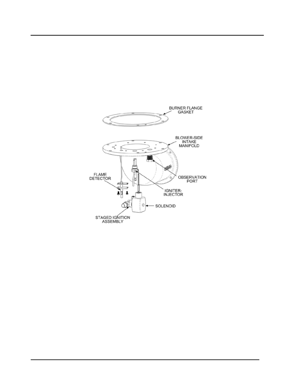
IGNITER-INJECTOR
The igniter-injector (part no. 58023) is located on the flange of the blower-side intake manifold located at
the bottom of the unit’s heat exchanger. In addition to providing the ignition spark required to light the
burner, the igniter-injector also contains a gas injector tube which connects to the staged ignition
assembly. Figure 6-1 shows the blower-side intake manifold removed from the heater and indicates the
locations of the igniter-injector, flame detector and other related components.
The igniter-injector may be hot, therefore, care should be exercised to avoid burns. It is easier to remove
the igniter-injector from the unit after the unit has cooled to room temperature.
Figure 6-1. Blower-Side intake Manifold (Shown Removed from Heater)
To inspect/replace the Igniter-Injector:
1. Set the ON/OFF switch on the control panel, to the OFF position. Disconnect AC power from the unit
2. Remove the side and rear panels from the unit.
3. Disconnect the cable from the igniter-injector (Figure 6-1).
4. Refer to the partial exploded view in Figure 6-1 and Figure 6-2. Using a 7/16” open-end wrench,
disconnect the compression nut securing the gas injector tube of the igniter-injector to the elbow of the
staged ignition solenoid assembly. Disconnect the staged ignition assembly from the igniter-injector.
5. Next, loosen and remove the igniter-injector from the intake manifold flange using a 1" open-end
wrench.
6. Check the igniter-injector for evidence of erosion or carbon build-up. If there is evidence of substantial
erosion or carbon build-up, the igniter-injector should be replaced. If carbon build-up is present, clean
the component using fine emery cloth. Repeated carbon build-up is an indication that the combustion
settings of the unit should be checked. Refer to Chapter 4 for combustion calibration procedures.