2 installing gas supply manometer, 3 accessing the analyzer probe port, Innovation series water heaters – AERCO Innovation (G-10-1350 to G-11-0563) User Manual
Page 42
GF
-
128
Innovation Series Water Heaters
Chapter 4
OMM-0079_0B
USER MANUAL
Initial Start-Up
Page 42 of 200
AERCO International, Inc.
· 100 Oritani Dr. · Blauvelt, NY 10913 · Ph.: 800-526-0288
07/21/11
4.2.2
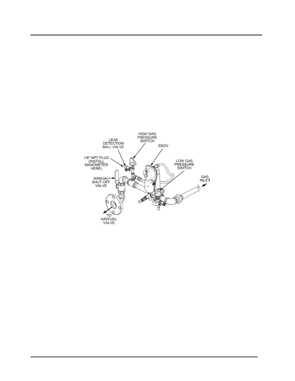
Installing Gas Supply Manometer
The gas supply manometer is installed in the gas train as follows:
1. Close the main manual gas supply shut-off valve upstream of the unit.
2. Remove the front door and left side panels from the heater to access the gas train components.
3. Remove the 1/8 inch NPT pipe plug from the leak detection ball valve on the downstream side of the
Safety Shut Off Valve (SSOV) as shown in Figure 4-1.
4. Install a NPT-to-barbed fitting into the tapped plug port.
5. Attach one end of the plastic tubing to the barbed fitting and the other end to the 16 inch W.C.
manometer.
Figure 4-1. 1/8 Inch Gas Plug Location
4.2.3
Accessing the Analyzer Probe Port
The unit contains a 1/8” NPT port at the rear of the exhaust manifold. This port is located above the
condensate drain connection as shown in Figure 4-2. Prepare the port for the combustion analyzer probe
as follows:
1. Refer to Figure 4-2 and remove the 1/8” NPT plug from the rear of the exhaust manifold.
2. If necessary, adjust the stop on the combustion analyzer probe so it will extend mid-way into the flue
gas flow. DO NOT install the probe at this time.