Electrical power guide – AERCO Innovation (G-10-1350 to G-11-0563) User Manual
Page 180
GF
-
5060
TAG-0045_0A
Electrical Power Guide
Page 180 of 200 AERCO International, Inc.
· 100 Oritani Dr. · Blauvelt, NY 10913 · Ph.: 800-526-0288
07/21/11
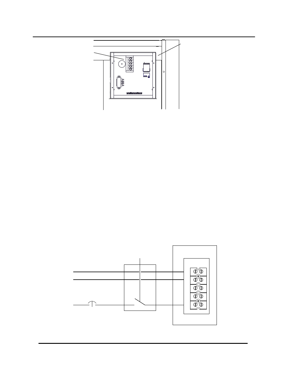
TERMINAL
BLOCK
UPPER RIGHT CORNER OF
FRONT PANEL
POWER
BOX
Figure 2. Terminal Block Location
Provisions for Service
Designers must provide emergency shutoffs and other devices to satisfy electrical codes. It is also
recommended to provide an electrical shutoff disconnect switch of suitable load carrying characteristics on
or near each BMK boiler. No electrical boxes or field components should be mounted to the surface of the
boiler or where they would interfere with the removal of the side or top panels for maintenance. The
disconnect switch should be mounted near the unit as illustrated in Figure 1. Wiring conduit, EMT, or other
wiring paths should not be secured to the unit, but supported externally. Electricians should be instructed as
to where the wiring conduit should be located, such as away from the relief valve discharge, drains, etc. All
electrical conduit and hardware should be installed so that it does not interfere with the removal of any
cover, inhibit service or maintenance, or prevent access between the unit and walls or another unit.
Boiler Wiring
A dedicated protected circuit should be provided from the power source to the boiler. No other electrical
devices should be permanently wired on the same circuit. An emergency switch (electrical shutoff) must be
in series with the power to the unit. Refer to Figure 3 for the wiring connections to the terminal block
contained in the unit’s Power Box.
Multiple Unit Wiring
Whenever multiple units are installed within the same mechanical spaces, electrical code requirements call
for a single electrical shutoff for emergency use. It is the responsibility of the electrical designer to comply
with local codes and regulations affecting an individual installation.
L1
GND
TERMINAL BLOCK
IN POWER BOX
DISCONNECT SWITCH
SINGLE-POLE, 20 AMP
L1
GND
120V/1/60Hz
1 POLE 20 AMP
CIR UIT BREAKER
120 VAC, 1 PHASE
NEU
NEU
Figure 3. 120V/1
Æ/60 Hz Wiring Schematic
Pg. 4 of 6