3 flame detector, Innovation series water heaters gf-128 – AERCO Innovation (G-10-1350 to G-11-0563) User Manual
Page 61
Chapter 6
Innovation Series Water Heaters
GF-128
Maintenance
USER MANUAL
OMM-0079_0B
07/21/11 AERCO International, Inc.
· 100 Oritani Dr. · Blauvelt, NY 10913 · Ph: 800-526-0288
Page 61 of 200
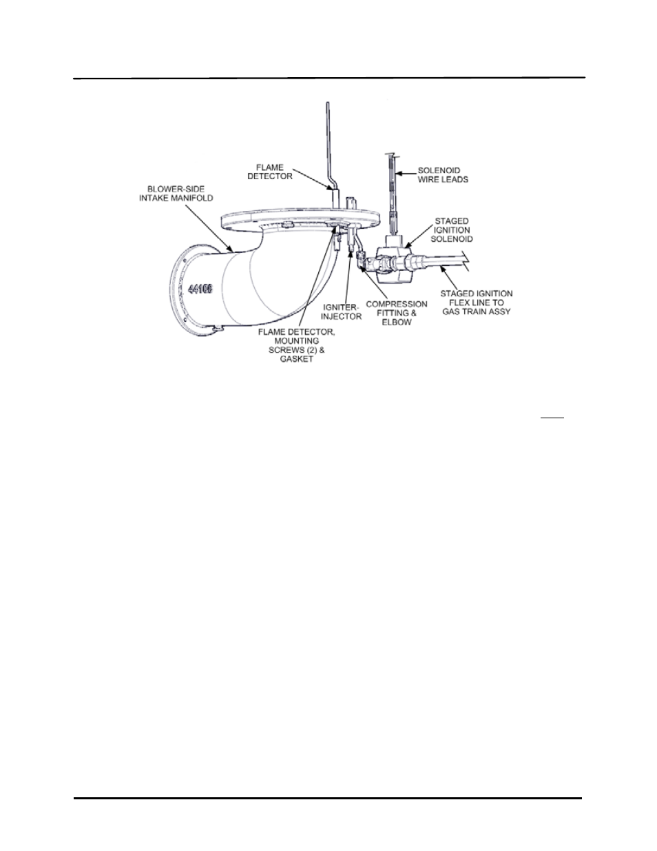
Figure 6-2. Igniter-Injector & Flame Detector Mounting Details
7. Prior to reinstalling the igniter-injector, a high temperature, conductive, anti-seize compound must be
applied to the threads.
NOTE
If a replacement igniter-injector (part no. 58023) is being installed, a compression nut
containing a built-in ferrule will be included with the replacement part. If needed, 3
indexing washers are also included. These washers may be needed to properly position
the gas injector tube of the igniter-injector so it does not contact other components or
assemblies of the unit.
8. Reinstall the igniter-injector on the intake manifold flange. Torque to 15 ft-lbs. Do not over tighten.
9. Connect the staged ignition assembly to the gas injector tube of the igniter-injector by securing the
compression nut to the elbow of the staged ignition assembly.
10. Reconnect the igniter-injector cable.
11. Reinstall the side and rear panels on the unit.
6.3
FLAME DETECTOR
The flame detector (part no. 66018) is also located on the flange of the blower-side intake manifold as
shown in Figures 6-1 and 6-2. The flame detector may be hot. Allow the unit to cool sufficiently before
removing the flame detector.
To inspect or replace the flame detector:
1. Set the ON/OFF switch on the control panel, to the OFF position. Disconnect AC power from the unit.
2. Remove the side and rear panels from the unit.
3. Disconnect the flame detector lead wire.