Innovation series water heaters gf-128 – AERCO Innovation (G-10-1350 to G-11-0563) User Manual
Page 63
Chapter 6
Innovation Series Water Heaters
GF-128
Maintenance
USER MANUAL
OMM-0079_0B
07/21/11 AERCO International, Inc.
· 100 Oritani Dr. · Blauvelt, NY 10913 · Ph: 800-526-0288
Page 63 of 200
5. Remove the two (2) screws securing the flame detector to the blower-side intake manifold (24234).
The flame detector is secured to the manifold with one (1) #10-32 screw and one (1) #8-32 screw.
6. Remove the flame detector and gasket from the blower side intake manifold flange.
7. Disconnect the cable from the igniter-injector which is also installed on the blower-side intake manifold
flange.
8. Using a 7/16” open-end wrench, disconnect the compression nut securing the gas injector tube of the
igniter-injector to the elbow of the staged ignition assembly (see Figure 6-2). Disconnect the staged
ignition assembly from the igniter-injector.
9. Next, loosen and remove the igniter-injector from the intake manifold flange using a 1" open-end
wrench.
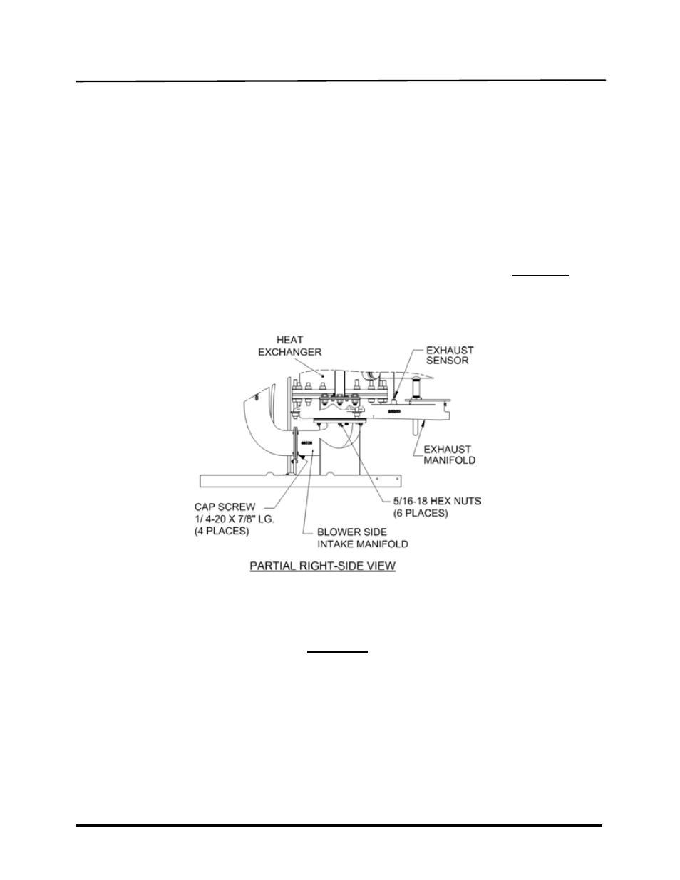
10. Refer to Figure 6-3. Loosen and remove the four (4) 1/4-20 cap screws securing the blower side of the
intake manifold (44106). DO NOT REMOVE the two 1/4-20 screws and nuts securing the manifold
support bracket.
Figure 6-3. Blower-Side Intake Manifold & Exhaust Manifold Locations
CAUTION
The intake manifold, burner and exhaust manifold assemblies weigh
approximately 25 pounds. Use care when removing these assemblies in the
following steps.
11. While supporting the blower-side intake manifold, loosen and remove the six (6) 5/16-18 hex nuts
securing it to the studs protruding from the exhaust manifold.
12. Carefully lower and remove the blower side intake manifold (44106), burner assembly (46023), burner
gasket (18899) and fiber frax gasket (124749) from the unit. See Figures 6-3 and 6-4.