8 air flow fault tests, Innovation series water heaters – AERCO Innovation (G-10-1350 to G-11-0563) User Manual
Page 54
GF
-
128
Innovation Series Water Heaters
Chapter 5
OMM-0079_0B
USER MANUAL
Safety Device Testing
Page 54 of 200
AERCO International, Inc.
· 100 Oritani Dr. · Blauvelt, NY 10913 · Ph.: 800-526-0288
07/21/11
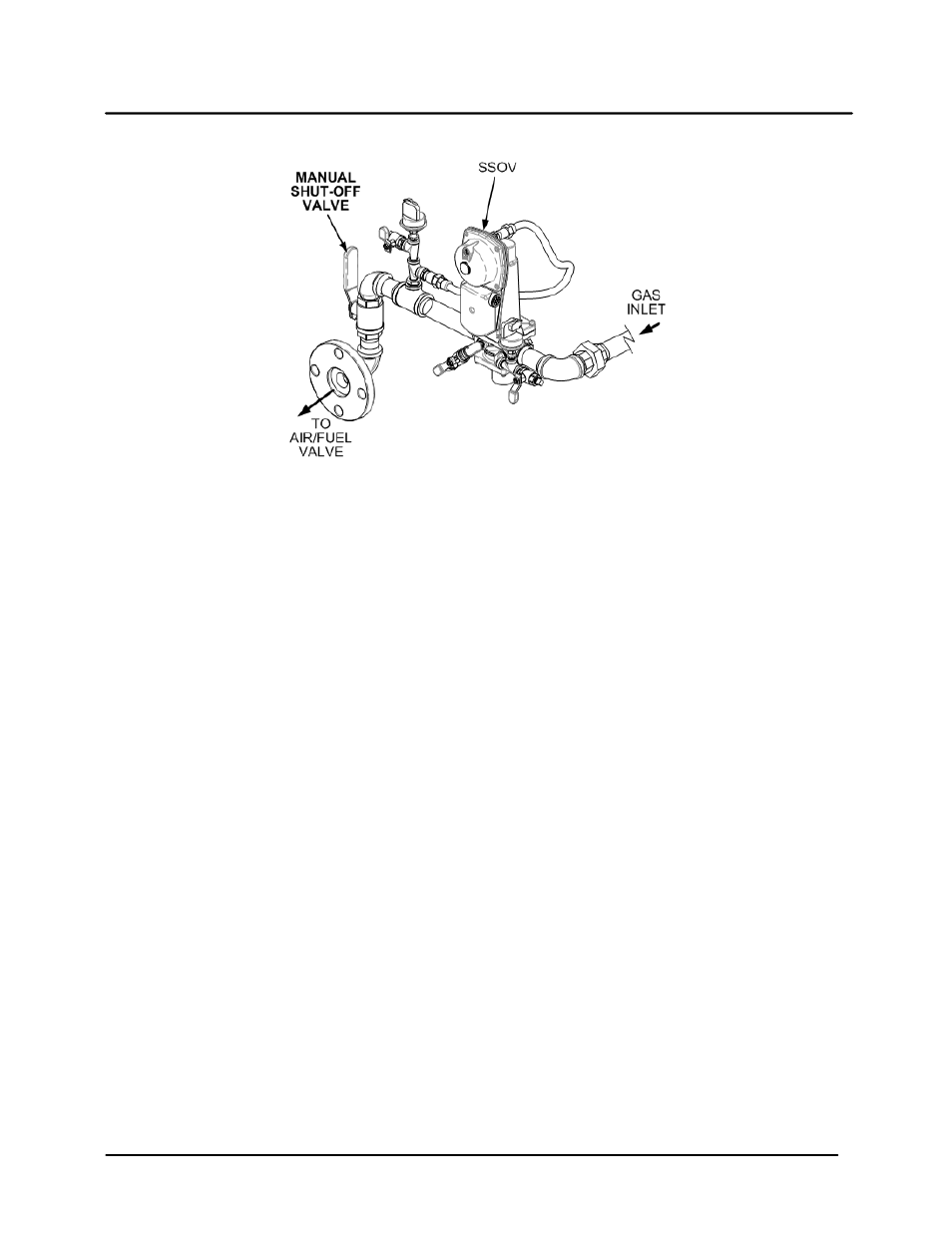
Figure 5-3. Manual Gas Shut-Off Valve Location
5.8
AIR FLOW FAULT TESTS
These tests check the operation of the Blower Proof Switch and Blocked Inlet Switch shown in Figure 5-4.
1. Disable the blower output drive voltage as follows:
(a) Press the MENU key until CONFIGURATION MENU is displayed.
(b)
Press the ▲ arrow key until the ANALOG OUTPUT function is displayed, then press the
CHANGE key.
(c)
Press the ▼ arrow key until OFF is displayed, then press the ENTER key.
2. Start the unit in the Manual Mode at a valve position of 25%.
3. The unit should shut down and execute an IGNITION RETRY cycle by performing the following steps:
(a) The unit will execute a 30 second re-ignition delay and display WAIT RETRY PAUSE.
(b) The unit will then execute a standard ignition sequence and display WAIT IGNITION RETRY.
4. The unit should perform two IGNITION RETRY cycles and then shut down on the third successive
ignition attempt. The unit will display AIRFLOW FAULT DURING PURGE.
5. Re-enable the blower output drive voltage by performing the following steps:
(a) Press the MENU key until CONFIGURATION MENU is displayed.
(b)
Press the ▲ arrow key until the ANA-LOG OUTPUT function is displayed, then press the
CHANGE key.
(c)
Press the ▲ arrow key until VALVE POSITION 0-10V is displayed, then press the ENTER key.
6. Once the unit has proved flame, turn off the blower by going to the Configuration Menu, Analog
Output menu item and select OFF.
7. The Blower Proof Switch will open and the blower should stop. The unit should shut down and display
AIRFLOW FAULT DURING RUN.
8. Go to the Configuration Menu, Analog Output item and select VALVE POSITION 0-10v.
9. Press the CLEAR button. The unit should restart.