Fuel system – Cub Cadet Yanmar 3TNV72 User Manual
Page 181
FUEL SYSTEM
7-20
TNV IDI Service Manual
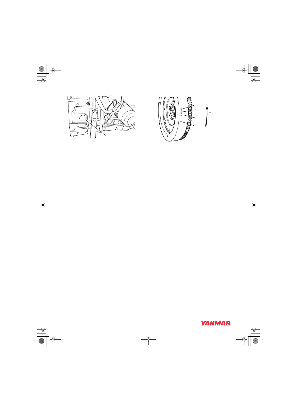
Checking and Adjusting Fuel Injection Timing
Figure 7-23
6. Typical flywheel markings are as shown in
(Figure 7-24).
Note: A typical flywheel will have multiple
timing grids depending on the number of
cylinders. Any grid and its corresponding
cylinder can be used to check the fuel
injection timing.
1 – 15° BTDC (Before Top Dead Center)
2 – 20° BTDC
3 – 25° BTDC
4 – Direction of Rotation
5 – TDC (Top Dead Center)
Figure 7-24
7. The flywheel shown in (Figure 7-24) is for a
Yanmar “Standard Specification” IDI engine.
Flywheels used on some “OEM Specific” IDI
engines may be marked differently. You should
contact that specific OEM for information on the
identification of the timing marks.
Note: The TDC (Top Dead Center) mark can
be identified by the cylinder numbers
stamped near the TDC mark
(Figure 7-24, (5)) on the flywheel.
8. If you are uncertain as to the timing degree
designation of the timing marks on the flywheel
timing grid, you can determine the timing
degree designation by measuring the timing
grid.
• First measure the distance between two of the
“longer” marks on the timing grid. (They are 5°
apart.) Then measure the distance from the
TDC mark to the first “longer” mark on the
timing grid. Divide that measurement by the
distance between the two “longer” marks. The
resulting answer will tell you how many
degrees there are between the TDC mark and
the first “longer” mark.
00020
(1)
(3)
(2)
(1)
(5)
(4)
0002071A
1
TNV_IDI_ServiceManual_(3TNV72 for YN only).book 20 ページ 2007年11月29日 木曜日 午後2時58分