Fuel system – Cub Cadet Yanmar 3TNV72 User Manual
Page 178
FUEL SYSTEM
TNV IDI Service Manual
7-17
Fuel Injection Pump
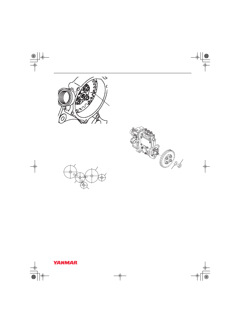
Figure 7-16
2. If installing the fuel injection pump on an engine
with the front gear case cover removed, the fuel
injection pump drive gear can be aligned with
the idler gear by aligning the stamped marks
(Figure 7-17, (A, B, C)) on the fuel injection
pump drive gear, idler gear, and crankshaft
drive gear. Ensure all three timing marks
(A, B, C) are aligned.
1 – Fuel Injection Pump Drive Gear
2 – Camshaft Drive Gear
3 – Optional Accessory Drive Gear
4 – Crankshaft Drive Gear
5 – Idler Gear
Figure 7-17
3. Install a new O-ring on the fuel injection pump
mounting flange. Apply some grease to the
O-ring to hold it in place during the installation
of the fuel injection pump.
Note: Ensure the tapered surface of the fuel
injection pump shaft is clean and dry.
4. Align the key on the fuel injection pump shaft
with the keyway in the fuel injection pump drive
gear hub. Reinstall the fuel injection pump into
the fuel injection pump drive gear and gear
housing. Install the pump retaining nuts
finger-tight.
5. Reinstall the fuel injection pump drive gear lock
washer (Figure 7-18, (2)) and nut
(Figure 7-18, (1)). Do not lubricate threads of
the nut or shaft. Hold the crankshaft pulley bolt
with a socket wrench and tighten the drive gear
nut to the specified torque. See Special Torque
Chart on page 7-7.
Figure 7-18
6. Align the reference marks (Figure 7-19, (1))
made during disassembly on both the fuel
injection pump mounting flange and gear case.
If installing a replacement fuel injection pump,
align the manufacturer-applied mark on the
pump mounting flange with the mark made on
the timing gear cover.
(1)
0002096
A
A
B
B
C C
0002190
(1)
(2)
(3)
(4)
(5)
0002183A
(1)
(2)
TNV_IDI_ServiceManual_(3TNV72 for YN only).book 17 ページ 2007年11月29日 木曜日 午後2時58分