Installation guidelines – Waterworks R.W. Atlas Exposed Thermostatic System with 8" Shower Rose, Extended Arm, and Metal Wheel Handles User Manual
Page 5
PRODUCT SUPPORT 800.927.2120 8am - 6pm EST
RW ATLAS
Exposed Thermostatic System with 8" Shower Rose
INSTALLATION GUIDELINES
Page 5 of 6
8.26.2014
These guidelines have been prepared for the professional contractor to aid in the installation of:
RW ATLAS EXPOSED THERMOSTATIC SYSTEM WITH 8" SHOWER ROSE WITH METAL WHEEL OR
LEVER HANDLE & WITH HANDSHOWER STYLE #'S RWXS21, RWXS31, RWXS41 & RWXS51
[RW21XS (UK), RW31XS (UK) RW41XS (UK) & RW51XS (UK)].
All dimensions are based on original specification and are subject to change and variation.
Please consult your Design Associate for current specifications.
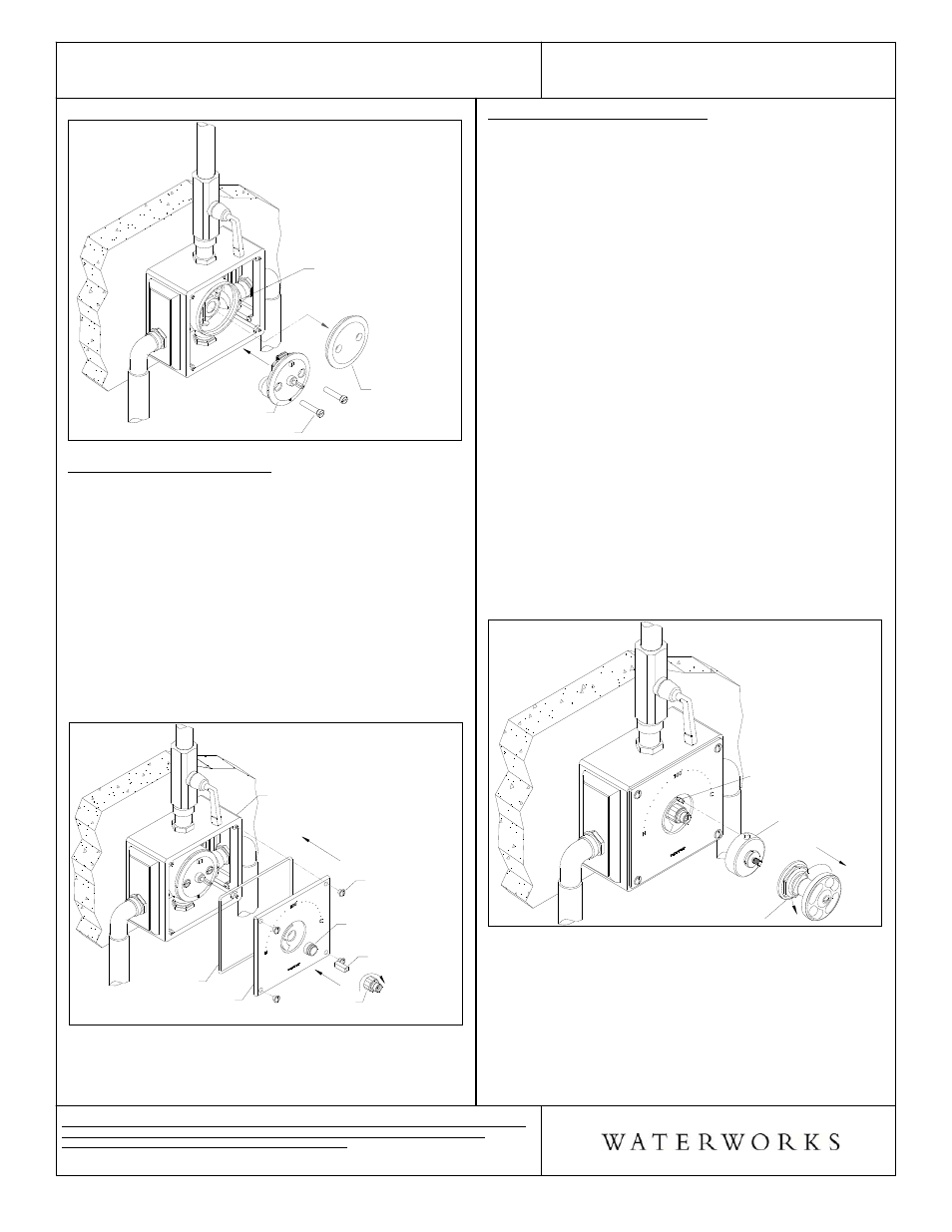
Figure - 07
FLUSH PLATE
SCREW
CARTRIDGE
SERVICE
STOP
TRIM PLATE INSTALLATION:
¾ See Figure - 08 for steps 29 - 31.
29. Attach trim plate to valve body using the 4 screws,
making sure the gasket is behind the plate. Note:
USE A LARGE SLOTTED SCREWDRIVER TO AVOID
DAMAGING SCREWS.
30. Thread the all thread adapter onto the cartridge
until it stops and insert the square tube over the
cartridge stem.
31. Thread the trim nut onto the all thread adapter until
it stops. Note: DO NOT OVER-TIGHTEN.
Figure - 08
GASKET
TRIM NUT
ADAPTER
ALL THREAD
ADAPTER
SQUARE TUBE
TRIM PLATE
VALVE BODY
SCREW
TEMPERATURE CALIBRATION:
¾ The risk of scalding exists until the installer has
properly calibrated the temperature setting.
¾ See Figure - 09 for steps 32 - 36.
32. Turn on the water supply and a wall valve to run
water through the valve and insert a bladed screw
driver into the square tube.
33. Slowly rotate the square tube clockwise to attain full
cold, then rotate it counter-clockwise to attain full
hot. Verify a full range of temperature exists. Note: It
is approximately 2 complete rotations from full cold
to full hot.
34. With water running, rotate the square tube to adjust
the temperature to the maximum desired bathing
temperature, verified with a thermometer. Turn the
water off and make sure not to change this
temperature setting.
35. Unthread the handle assembly from the limit stop
assembly and loosen the 4 set screws on the limit
stop.
36. Insert the limit stop assembly onto the trim nut
making sure the limit stop pin (shown removed)
makes contact with the limit stop on the trim plate,
then tighten the 4 set screws.
Figure - 09
HANDLE ASSEMBLY
LIMIT STOP
ASSEMBLY
LIMIT STOP PIN
[SHOWN REMOVED]