Installation guidelines, Rw atlas – Waterworks R.W. Atlas Exposed Thermostatic System with 8" Shower Rose, Extended Arm, and Metal Wheel Handles User Manual
Page 2
PRODUCT SUPPORT 800.927.2120 8am - 6pm EST
RW ATLAS
Exposed Thermostatic System with 8" Shower Rose
INSTALLATION GUIDELINES
Page 2 of 6
8.26.2014
These guidelines have been prepared for the professional contractor to aid in the installation of:
RW ATLAS EXPOSED THERMOSTATIC SYSTEM WITH 8" SHOWER ROSE WITH METAL WHEEL OR
LEVER HANDLE & WITH HANDSHOWER STYLE #'S RWXS21, RWXS31, RWXS41 & RWXS51
[RW21XS (UK), RW31XS (UK) RW41XS (UK) & RW51XS (UK)].
All dimensions are based on original specification and are subject to change and variation.
Please consult your Design Associate for current specifications.
¾ Make sure there is enough clearance after the floors
and walls have been finished in the shower area.
1.
Run well supported 3/4" hot and cold copper supply
lines for maximum flow.
2. Verify the supplies are secure and level. The inlets
must have a spread of 11-1/2"MIN to 11-3/4"MAX.
Make sure the hot supply is on the left and the cold
supply is on the right. Cap off supplies and outlet
and check for leaks.
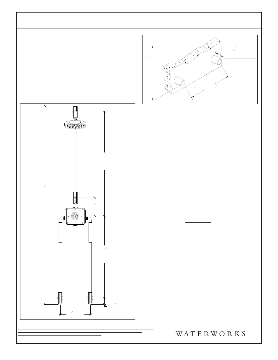
3. Cut the copper supply lines so they extend 15/16"
from the finished wall. (See Figure - 02).
Figure - 01
11
1
2
"MIN
11
3
4
"MAX
32
5
8
"
[829mm]
VALVE TO
INLETS
2
1
2
"
[63mm]
41
1
2
"
[1053mm]
ADJUSTABLE
CAN BE FIELD CUT
7
3
8
"
[187mm]
79
1
16
"
[2008mm]
OVERALL
ADJUSTABLE
Figure - 02
11
1
2
" MIN - 11
3
4
" MAX
32
5
8
" TO CENTER
OF VALVE BODY
15
16
" FROM
FINISHED WALL
CO
LD
SU
PP
LY
HO
T
SU
PP
LY
EXPOSED VALVE INSTALLATION:
¾ See Figure - 03 for Steps 5-12.
¾ Note: This installation step will require 2 persons.
4. Unthread and remove the compression nuts and
compression rings, along with escutcheons and o-
rings from each inlet connection.
5. Slide the o-ring, escutcheon, compression nut and
compression ring over each inlet supply pipe,
making sure the threading on the compression nut is
facing outwards.
6. Loosen the knurled collars and thread the inlet legs
into the valve body until they stop, then un-thread
enough so that they align with the supply pipes and
outlet tube (MAXIMUM 3 ROTATIONS). Note that
the elbow seal is created by internal o-rings and
NOT by fully tightening the elbow.
7. Position the inlet legs onto the supplies along with
the valve body until they are fully seated into the
elbow and then hand tighten the compression nuts.
Slide the escutcheon back towards the wall; and if
the gap is too large, as to where the escutcheon
slides off the compression nut, cut the supply pipes
accordingly.
8. With the valve body level and up against the wall,
mark the 4 mounting hole locations through the
holes that are on the back plate of the valve body.
9. Loosen the compression nuts and remove the inlet
legs and valve body.
10. Drill the wall for the 4 wall anchors provided and
install them.
11. Re-install the inlet legs along with the valve body
onto the supply pipes, then , using a wrench, tighten
the compression nuts fully. Tighten the knurled
collars so that they are tight against the side of the
valve body. Make sure the escutcheons are against
the wall, with the o-ring behind it.