Viewing the circuit configuration, Viewing the circuit conþguration -22 – Cabletron Systems CSX400 User Manual
Page 86
CSX WAN Configuration
4-22
Configuring the Frame Relay Protocol
Viewing the Circuit Configuration
The Frame Relay protocol can be set to two different states: ansiT1617 with LMI
(Local Management Interface) or noLmiConÞgured. A frame relay network uses
circuits as connections to the other points on the network. When an LMI is
conÞgured for your interface, the circuits will automatically be listed in the Frame
Relay Circuit Table. The switch will report the circuits to your device. If there is no
LMI on your connection, you will have to manually add the circuits. The Frame
Relay Circuit Table displays the circuits that are currently deÞned on all the frame
relay interfaces conÞgured on the device.
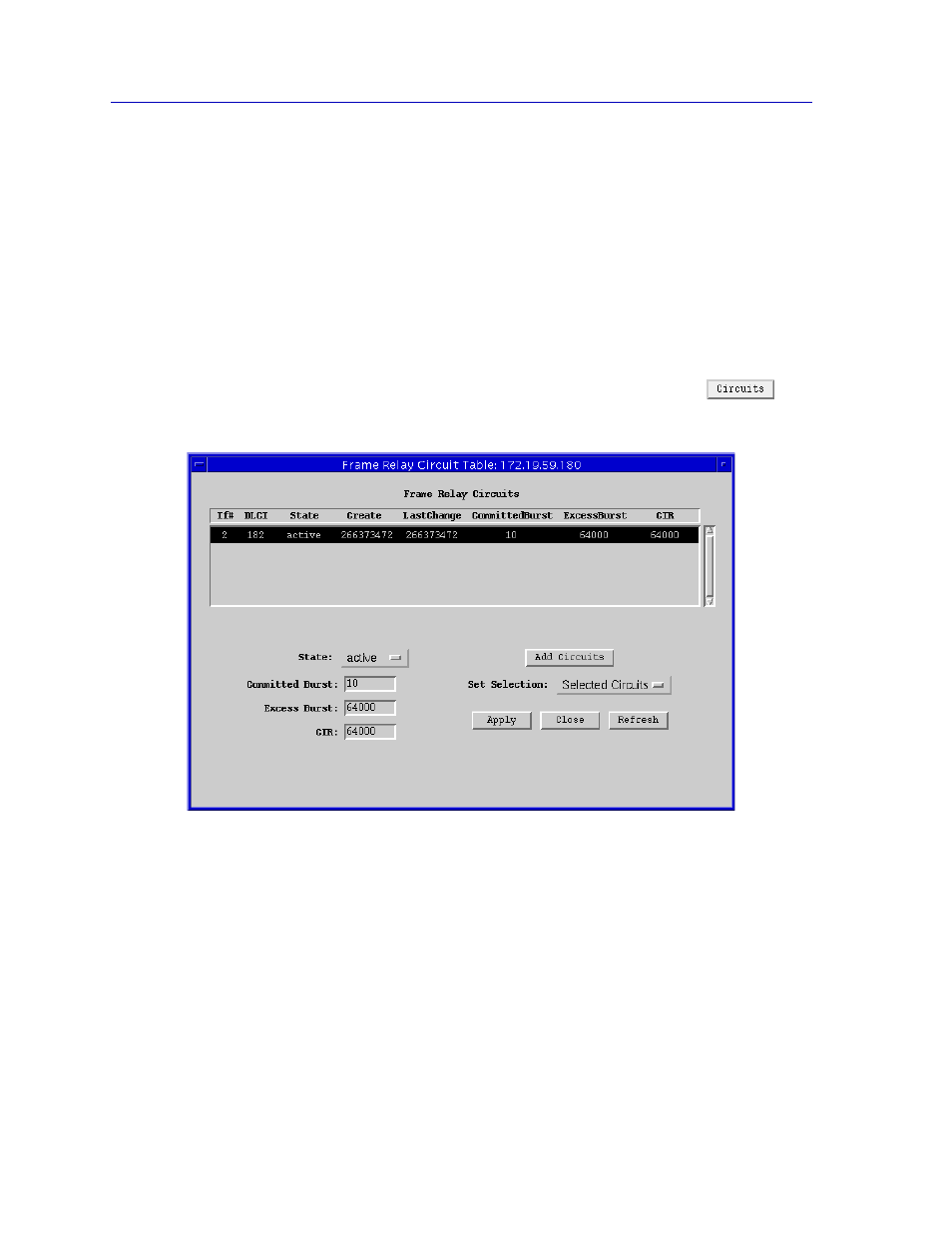
To view the Frame Relay Circuit Table window:
1.
From the Frame Relay Protocol Configuration window, click on
. The
Frame Relay Circuit Table,
, will be displayed.
Figure 4-9. The Frame Relay Circuit Table Window
The following Þelds are displayed in the Frame Relay Circuit Table. The State,
Committed Burst, Excess Burst, and CIR Þelds are user-conÞgurable.
If#
Displays the number of the interface this virtual circuit is layered upon.
DLCI
The Data Link Connection IdentiÞer for the virtual circuit. This is a routing ID
that links the logical port to a virtual connection on the physical frame relay port.
This number is usually assigned by your frame relay provider. The CSX200 can
support up to 4 virtual circuits and the CSX400 can support up to 32 per interface.