Figure 5. front view (bezel removed), Bfigure 6. control panel – Kontron TIGW1U Carrier Grade Server User Manual
Page 17
Kontron Carrier Grade Server TIGW1U
December 2009
Product Guide, rev. 1.3
17
Features—TIGW1U server
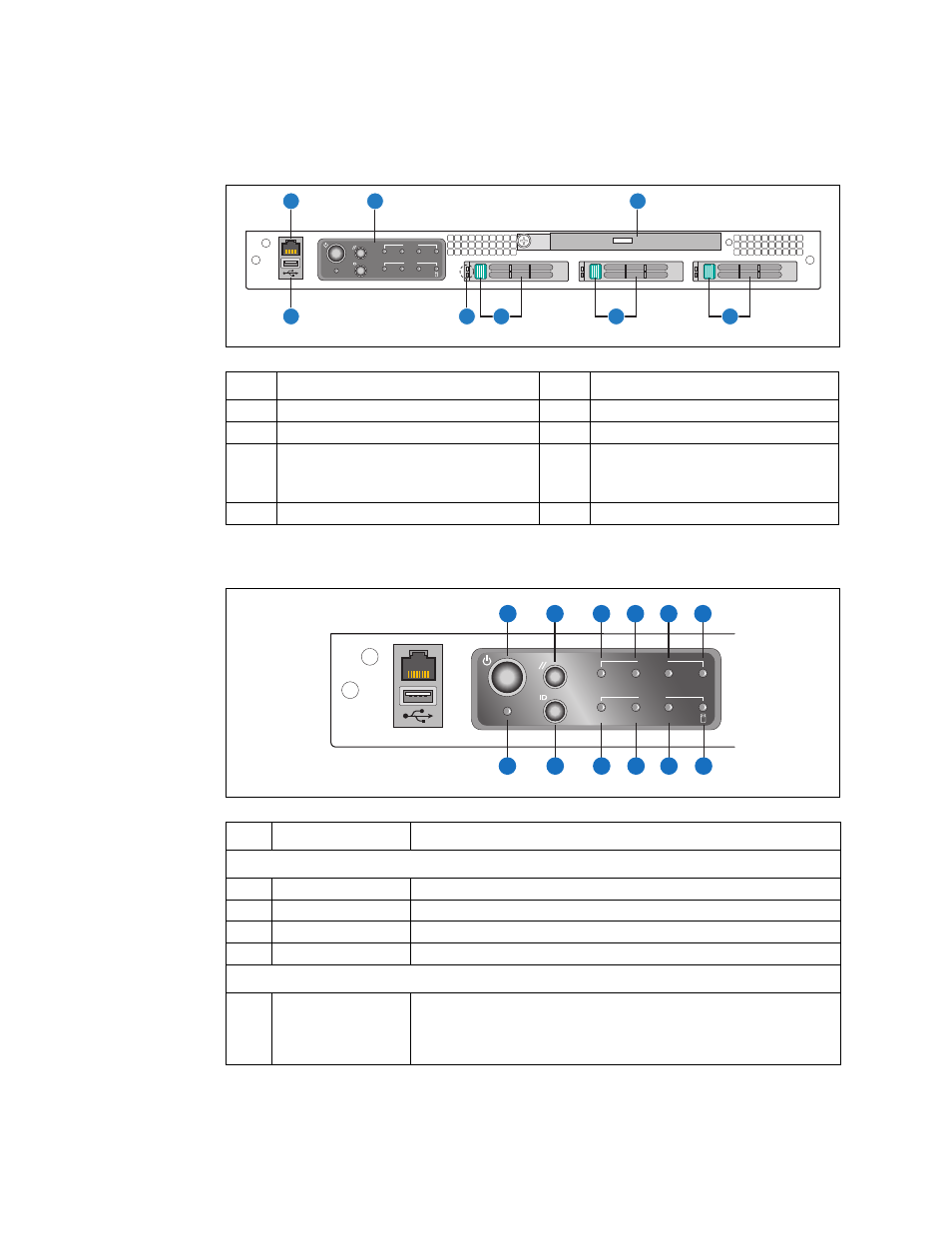
Figure 5.
Front View (Bezel Removed)
Item
Description
Item
Description
A
RJ45 serial port (COM2/Serial B)
E
Drive bay 1 and handle
B
Front panel control switches and LEDs
F
Drive bay 2 and handle
C
Optical drive
G
HDD LEDs
top = fault (amber)
bottom = activity (ready/green;
active/blinking green)
D
Drive bay 0 and handle
H
USB port 2
AF000807
A
H
G
C
F
E
D
Alarms
Status
ID
ON
NIC
CRT
MNR
PWR
MJR
B
Figure 6.
Control Panel
Item
Feature
Description
Front Panel Switches
A
Power switch
Toggles the system power
B
Reset switch
Resets the system
K
ID switch
Toggles the system ID LED
L
NMI switch
Asserts NMI to the server board
Front Panel Alarm LEDs and Relays
C
Critical (amber)
When continuously lit, this indicates a Critical System Fault. A critical system
fault is an error or event with a fatal impact to the system. In this case, the
system cannot continue to operate. An example is the loss of a large section
of memory, or other corruption, that renders the system non-operational.
The front panel critical alarm relay engages.
AF000808
A
B
D
C
E
F
L
G
H
I
J
K
Alarms
Status
ID
ON
NIC
CRT
MNR
PWR
MJR