Kontron COMe-cPV2(v1.4) User Manual
Page 39
Kontron microETXexpress-PV User’s Guide
35
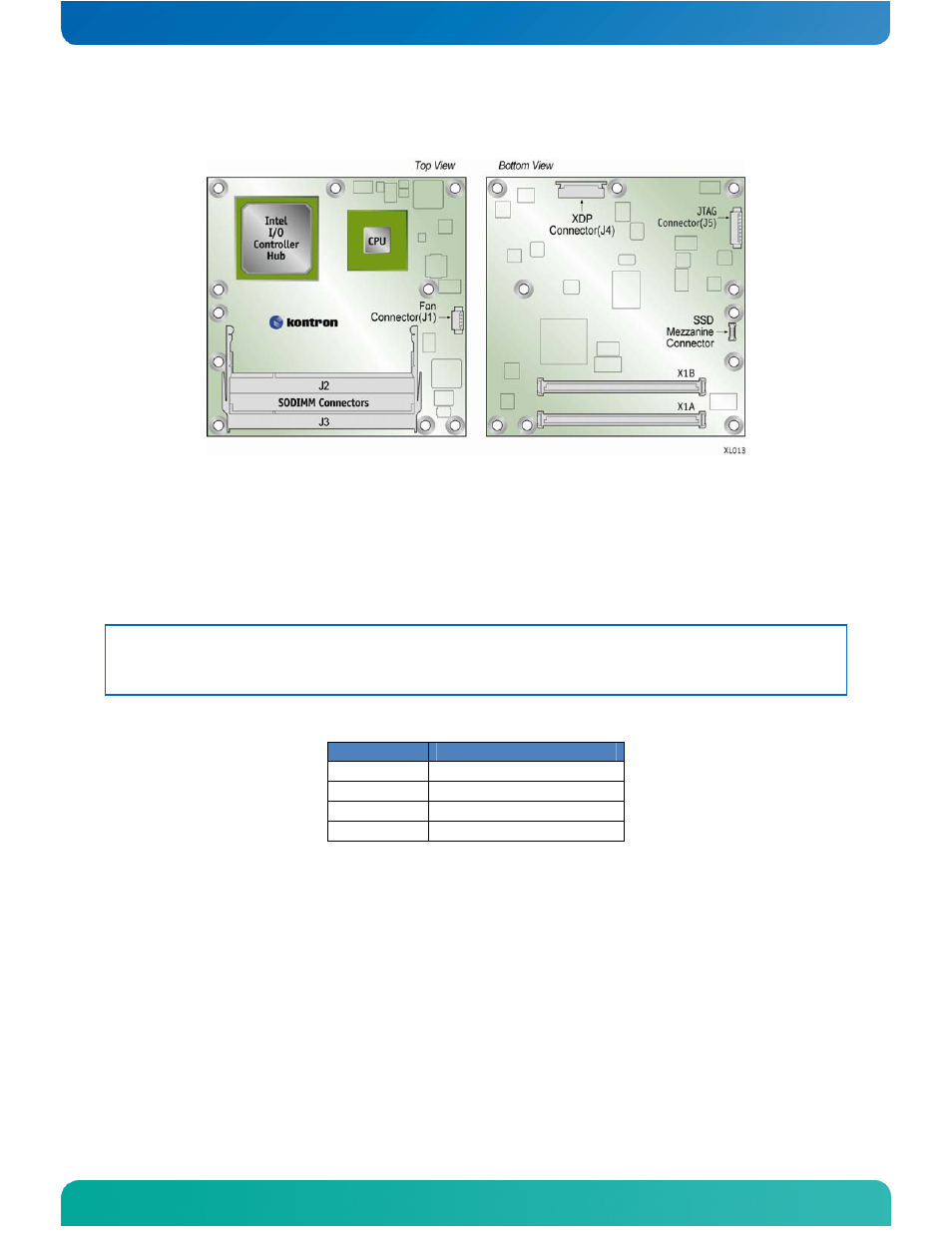
Figure 4: Onboard Connectors
J1 - CPLD Debug
4.1.2
Connector J1 – Fan
J1 is the 4-pin connector for a fan. J1 can be configured in the BIOS setup.
See Section 6.3, “Onboard Fan Connector” for more detailed information.
Although the module is functional without active cooling, it is advised that
a minimal airflow be maintained within the system to ensure components
do not overheat.
Table 9: J1 Fan Connector Pin-Out
Pin
Name
1 FAN_TACH
2 FAN_V_IN
3 FAN_GND
4 V_5V
4.1.3
Connectors J2 and J3 – SODIMM DDR2 Memory Sockets
This design supports up to 2 GBytes (single channel) of DDR2 memory with two
200-pin sockets.
4.1.4
Connector J4 - XDP
The eXtended Debug Port (XDP) connector is a 24-pin connector used for
debugging the board.
- CP3003-SA uEFI BIOS (72 pages)
- CP3003-SA (36 pages)
- CP3002 (38 pages)
- CP3002-RC uEFI (64 pages)
- CP-RIO3-05 (42 pages)
- CP3002-RC (30 pages)
- CP342 (52 pages)
- CP930 (46 pages)
- CP932 (52 pages)
- CP346 (72 pages)
- CP384 (66 pages)
- CP383 (74 pages)
- CP382 (58 pages)
- CP381 (60 pages)
- CP372 (64 pages)
- CP371 (60 pages)
- CP-RIO3-04S (38 pages)
- CP390 (36 pages)
- CPS3410 (9 pages)
- CPS3402 (9 pages)
- CPS3105 (9 pages)
- CPS3101 (9 pages)
- CPS3003-SA (19 pages)
- PB-SIO4 (34 pages)
- PB-SIO4A (34 pages)
- PB-DOUT8 (34 pages)
- VMOD-2 (82 pages)
- VSBC-32 (110 pages)
- VM42 (62 pages)
- Bootstrap Loader (24 pages)
- VMP1 with Netbootloader (120 pages)
- VMP1 (106 pages)
- NetBootLoader (86 pages)
- VMP2 (142 pages)
- VMP3 (154 pages)
- CP-RIO6-923 (32 pages)
- CP-RIO6-923-F (32 pages)
- CP-RIO6-001 (28 pages)
- CP-RIO6-001-HD-VGA (46 pages)
- CP-RIO6-M (20 pages)
- CP-RIO6-B (28 pages)
- CP6925 (42 pages)
- CP6002 uEFI BIOS (76 pages)
- CP6002 IPMI (40 pages)
- CP6002 (42 pages)