1 vme boot, 2 rom boot, 3 protective ground - signal ground – Kontron VM162 User Manual
Page 65: 4 vme sysres, Vme boot -5, Rom boot -5, Protective ground - signal ground -5, Vme sysres* -5
VM162/VM172
Chapter 3 Configuration
Juli 23, 1997
Page 3- 5
© PEP Modular Computers
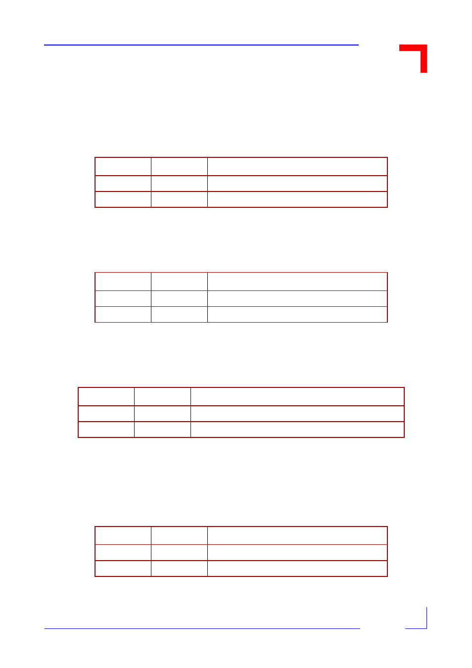
3.2.1 VME Boot
The VM162/VM172 normally boots from the FLASH memory on the DM60x piggyback. In some ap-
plications it may be useful to boot either from the VMEbus or the optionally assembled EPROM.
3.2.2 ROM Boot
3.2.3 Protective Ground - Signal Ground
3.2.4 VME SYSRES*
As long as the 5V supply is not within the VMEbus specification, the VM162/VM172 uses the VMEbus
RESET line. This behaviour may not be wanted in multi-master configurations and can be disconnected.
Jumper
Setting
Description
J1
Open
Boot from VMEbus enabled
Set
Boot from VMEbus disabled
Default
Jumper
Setting
Description
J2
Set
Boot from boot ROM enabled
Open
Boot from boot ROM disabled
Default
Jumper
Setting
Description
J8
Set
Protective ground connected to signal ground
Open
Protective ground disconnected from signal ground
Default
Jumper
Setting
Description
J10
Set
On-board RESET generator to VME
Default
Open
On-board RESET generator disconnected from VME