4 vme address map from the vme side, Table 2.7: vme address map, Vme address map from the vme side -12 – Kontron VM162 User Manual
Page 34
VM162/VM172
Chapter 2 Functional Description
Page 2- 12
© PEP Modular Computers
Juli 23, 1997
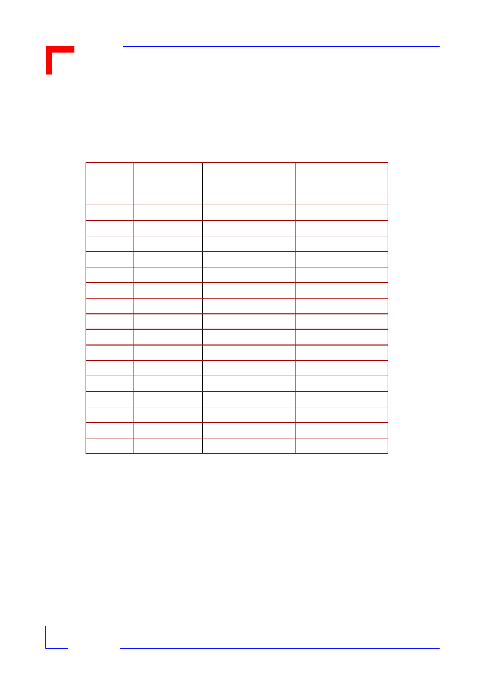
2.5.4 VME Address Map from the VME Side
The Table below shows the VME board address map for external Master access dependent on the setting
of the board address bits within the VME Control/Status Register.
Table 2.7: VME Address Map
Note: All of the possible board address ranges are located in VME A24/D16 addressing mode. It is en-
abled for supervisor/user data access in accordance to AM codes 3D and 39.
Board
Address
Bits
BADR[3-0]
Board VME Base
Address (HEX)
Mailbox Interrupt Reg.
Address Range
(HEX)
Dual-ported SRAM
Address Range
(HEX)
0
00 00 00
00 00 00 - 00 1F FF
00 20 00 - 0F FF FF
1
10 00 00
10 00 00 - 10 1F FF
10 20 00 - 1F FF FF
2
20 00 00
20 00 00 - 20 1F FF
20 20 00 - 2F FF FF
3
30 00 00
30 00 00 - 30 1F FF
30 20 00 - 3F FF FF
4
40 00 00
40 00 00 - 40 1F FF
40 20 00 - 4F FF FF
5
50 00 00
50 00 00 - 50 1F FF
50 20 00 - 5F FF FF
6
60 00 00
60 00 00 - 60 1F FF
60 20 00 - 6F FF FF
7
70 00 00
70 00 00 - 70 1F FF
70 20 00 - 7F FF FF
8
80 00 00
80 00 00 - 80 1F FF
80 20 00 - 8F FF FF
9
90 00 00
90 00 00 - 90 1F FF
90 20 00 - 9F FF FF
A
A0 00 00
A0 00 00 - A0 1F FF
A0 20 00 - AF FF FF
B
B0 00 00
B0 00 00 - B0 1F FF
B0 20 00 - BF FF FF
C
C0 00 00
C0 00 00 - C0 1F FF
C0 20 00 - CF FF FF
D
D0 00 00
D0 00 00 - D0 1F FF
D0 20 00 - DF FF FF
E
E0 00 00
E0 00 00 - E0 1F FF
E0 20 00 - EF FF FF
F
F0 00 00
F0 00 00 - F0 1F FF
F0 20 00 - FF FF FF