EFCO 5500X Outside Glazed User Manual
Page 55
EFCO 2012
Page 55
Series 5500 XTherm
™
Curtain Wall Assembly and Installation Instructions
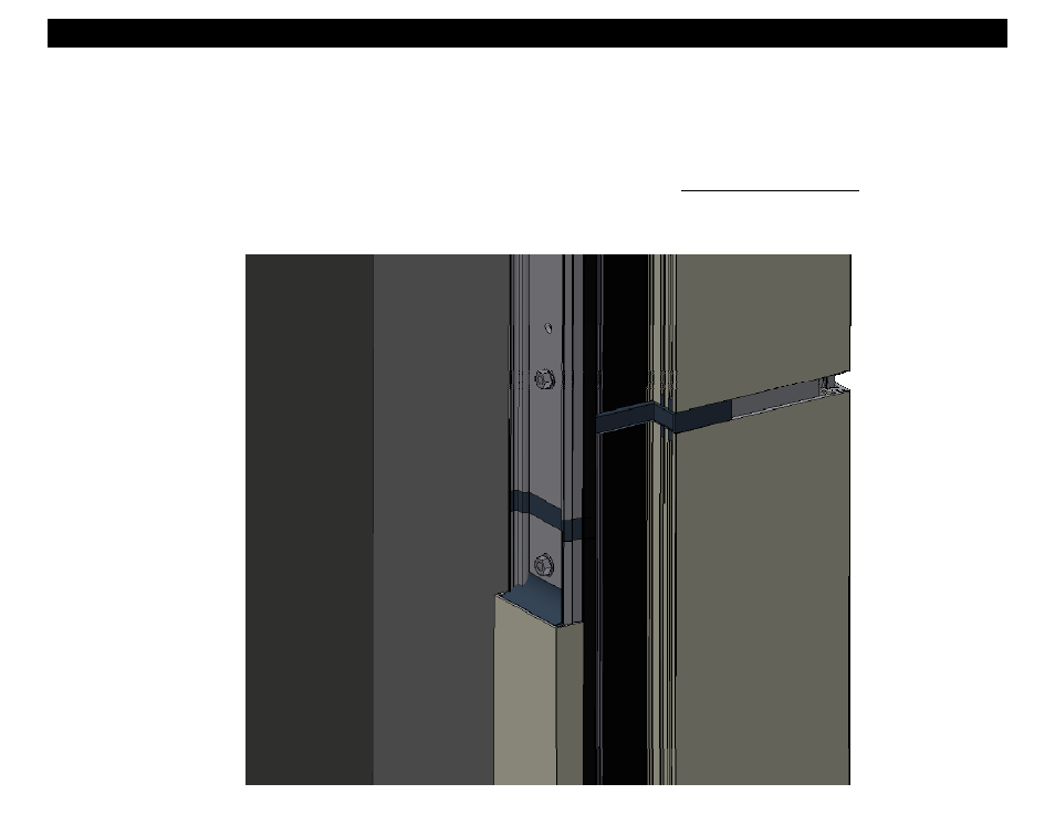
Section 14 - Vertical Splice Joints
1. Splice Joints should occur at the spandrel areas (if Possible). Refer to approved final shop drawings fro actual locations.
2. Depending on the specific job requirements, splice sleeves may be shop or field assembled in the top of the lower mullion. If materials are field fabricated,
use the following assembly instructions. Where head clearance is insufficient to allow the top mullion to be lifted over the splice sleeve, a retractable sleeve
will be used. The sleeve must be taped into the bottom of the top mullion and dropped down to the stop screw in the mullion below.
3. General Note: The following page depicts a splice joint of 1/2”. The required joint width must be determined in the design stage and shown on the approved
Final Shop Drawings, on a job by job basis. Keep in mind that a typical curtain wall can accommodate 1/4” total vertical movement. The splice joint , hori-
zontal glazing pocket immediately above the splice, and slotted wind load anchors, must all be considered when vertical movement exceeds 1/4”.
4. Refer to this section for cover splice, pressure plate splice relative locations, and sealing instructions.
5. Once a final check of expansion joint placement and mullion position is made, the final match drilling of mullion through anchor holes may be complete.