Series 5500 xtherm – EFCO 5500X Outside Glazed User Manual
Page 45
EFCO 2012
Page 45
Series 5500 XTherm
™
Curtain Wall Assembly and Installation Instructions
Note: Care should be
taken when handling
the frames to avoid
damaging the edges
of the fillers. Blocks
of wood used with
“C” clamps should be
employed to aid in
snapping together the
filler and the
mullions.
Apply joint plugs into the
open areas adjacent to the
horizontals as shown in
Section 8, starting on page 29.
NOTE: On long runs,
check overall frame
dimensions at every
fifth opening to avoid
dimensional build-up.
The commercial cut
length tolerance is +/-
1/16”. It is critical to
check every fifth unit
for location relative to
established
benchmarks.
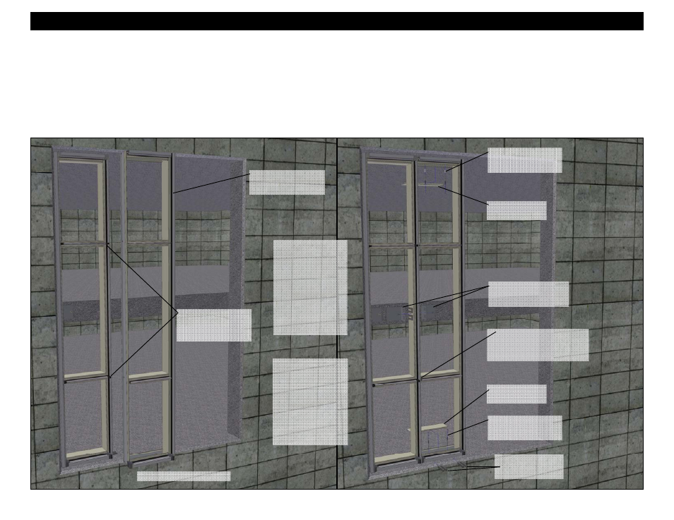
Section 12 - Install Twin Span Frame Components
Typical Intermediate Frame
Set the frame into the
opening and shim
level and plumb.
Snap fillers in to
head and sill.
Seal the vertical at all
horizontal locations.
(See Figure 2 and 3
on page 17).
Snap fillers in to
head and sill.
Anchor the frame into
the opening as shown
on pages 33 and 34.
Anchor the frame into
the opening as shown
on pages 33 and 34.
Apply intermediate wind
load anchors. See
pages 46 through 47.
Apply dead load
shims at anchors
and below verticals
13. Apply sealant to the verticals as shown in Figures 2 and 3 on page 17 to seal the vertical and fillers at the intersection of the heads, sills, and intermediate
horizontals. This seal should be made immediately before snapping the filler and the vertical mullions together.
14. Set the intermediate frame into the opening mating the filler with the intermediate vertical until the filler and vertical snap together.
15. Use dead load shims at the sill to level the frame, and make all necessary adjustments to properly locate the frame to established benchmarks.
16. After the frame is plumb and all adjustments have been made, match drill through the holes in the head and sill into the surrounding substrate, and apply the
anchor bolts at the head and sill. Anchor bolt size, type, quantity, and location vary. Refer to the final approved shop drawings for more information. The
anchors at the head require an anchor bolt sleeve to accommodate thermal expansion and contraction, and building movements.
17. Apply intermediate wind load anchors as shown and noted on pages 46 and 47.