Series 5500 xtherm – EFCO 5500X Outside Glazed User Manual
Page 43
EFCO 2012
Page 43
Series 5500 XTherm
™
Curtain Wall Assembly and Installation Instructions
Section 12 - Install Twin Span Frame Components
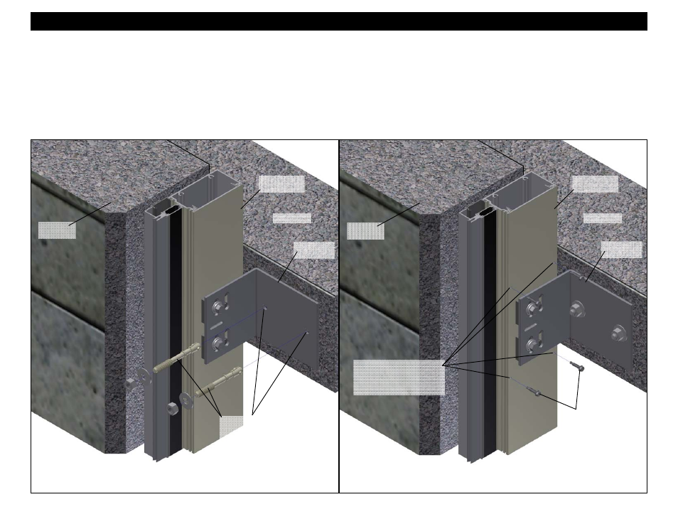
9. Match drill the face of the slab through the holes provided in the anchor and attach the assembly to the structure. Refer to the final approved shop drawings,
and the bolt manufacturer’s installation instructions for more information. See Figure 50 below.
10. The filler must be attached to the main section of the mullion assembly at the jamb anchor locations. Once the anchor is secured to the structure in its final
position, drill (4) 1/8” pilot holes in the filler and main section of the vertical. At least (2) holes 1” above and (2) holes 1” below the wind load anchor clip are
required. Refer to the final approved shop drawings for size, quantity, and additional information. Attachment 1” above and below the anchor is required to
allow free movement between the anchor and mullion during live load deflections and thermal movements. The screws must not interfere with this movement.
See figure 52 on page 44 for addition dimensions and information.
11. Attach the filler and mullion sections together with fasteners as noted in the final approved shop drawings. See Figure 53 on page 44.
Figure 50
Jamb Section
Drill (4) 1/8” pilot holes in
the filler and main section
of the vertical.
(See Figure 52 on page 44).
Wind Load
Anchor
Perimeter
O.G. Mullion
Floor Slab
Figure 51
Jamb Section
Jamb
Condition
Match drill the face of the slab
through the holes provided in
the anchor and attach the
assembly to the structure.
Wind Load
Anchor
Jamb
Condition
Perimeter
O.G. Mullion
Floor Slab
STK6 #12-14 X 1”
HWH SMS ZC TEK 3