Series 5500 xtherm – EFCO 5500X Outside Glazed User Manual
Page 46
EFCO 2012
Page 46
Series 5500 XTherm
™
Curtain Wall Assembly and Installation Instructions
Section 12 - Install Twin Span Frame Components
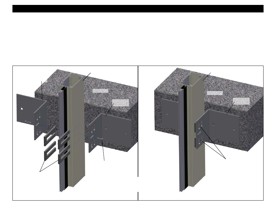
18. Once the frame has been properly set, and securely anchored at the head and sill, place the intermediate wind load anchor flush with the face of the slab and
with each side of the intermediate mullion shimming between the anchor and mullion as shown in Figure 54 below. Refer to the final approved shop
drawings for exact anchor placement and minimum bolt edge distance requirements. Note it is critical that the tops of the anchors are aligned with each
other so that the anchor bolts can be inserted through each anchor and the mullion after the mullion has been matched drilled as noted in Figure 55 below.
19. Apply anchor alignment screws (
STK6 #12-14 X 1
” HWH SMS ZC TEK 3) to hold the anchors temporarily in place. These fasteners must be removed after
final anchor attachment.
20. Ensure the anchors are pressed firmly against the face of the floor slab and match drill the mullion through the center of two of the slots in the anchors for the
though bolt connection. Choose the set of slots which will allow the anchor bolt to be placed a minimum of 1” from the back of the mullion to clear any steel
reinforcement that may be required on the project. For steel reinforcement, anchor configuration, bolt, and hole size requirements, refer to the final approved
shop drawings.
Figure 54
Intermediate Section
Place anchors flush
with face of slab and
the side of the mullion.
Apply a temporary anchor
attachment screw (STK6 #12-
14 X 1” HWH SMS ZC TEK 3)
Match drill through
center of set of slots
with the best access.
Wind Load
Anchor
Intermediate
O.G. Mullion
Floor Slab
Floor Slab
Wind Load
Anchor
Apply shims between
the mullion and anchor.
Figure 55
Intermediate Section
Intermediate
O.G. Mullion
Set tops of anchors to the
same elevation height for
match drilling and through
bolting of anchor system.