Carrier 16DF013-050 User Manual
Page 49
Solution Analysis —
Laboratory analysis of a solution
sample gives indication of change in solution alkalinity and
depletion of inhibitor, and may indicate the degree of ma-
chine leak tightness.
Have the solution analyzed at least once a year or when-
ever there is an indication of a noncondensable problem. Take
the sample from the solution pump service valve while the
machine is running (see Solution or Refrigerant Sampling
section, page 48). The sample concentration should be be-
tween 58% and 62% by weight for best results.
Solution analysis should be done by an approved lab-
oratory. The analysis interpretation and the adjustment rec-
ommendations should be made by a trained absorption
specialist.
Inhibitor —
Lithium chromate inhibitor is charged into
the machine with the initial charge of lithium bromide. The
inhibitor is used in conjunction with alkalinity control to mini-
mize the amount of noncondensables normally generated within
the machine. Excessive noncondensable generation inter-
feres with machine performance.
The inhibitor is gradually depleted during machine opera-
tion and occasional replenishment is necessary. Solution al-
kalinity also changes over a period of time and must be ad-
justed (see Solution Analysis, this page).
IMPORTANT: Altering the inhibitor or using solution
and internal surface treatments not specified by the equip-
ment manufacturer may result in performance deterio-
ration and damage to the absorption machine.
Adding Octyl Alcohol —
Octyl alcohol may be re-
quired when leaving chilled water temperature starts to rise
above design temperature without alteration of the control
set point. Since the rise in temperature can also be caused by
fouled tubes or other problems, use the following procedure
to determine whether a lack of octyl alcohol is the cause:
NOTE: Add octyl alcohol only during cooling operation.
1. Remove a sample of solution from the solution pump serv-
ice valve (see Solution or Refrigerant Sampling section,
page 48). If the solution has no odor of alcohol (very pun-
gent), add about
1
⁄
2
gal. (2 L) of octyl alcohol.
The addition of octyl alcohol also may be required after
the machine has been evacuated or after an extended pe-
riod of operation.
Use only octyl alcohol. Other types of alcohol have
a detrimental effect on machine performance.
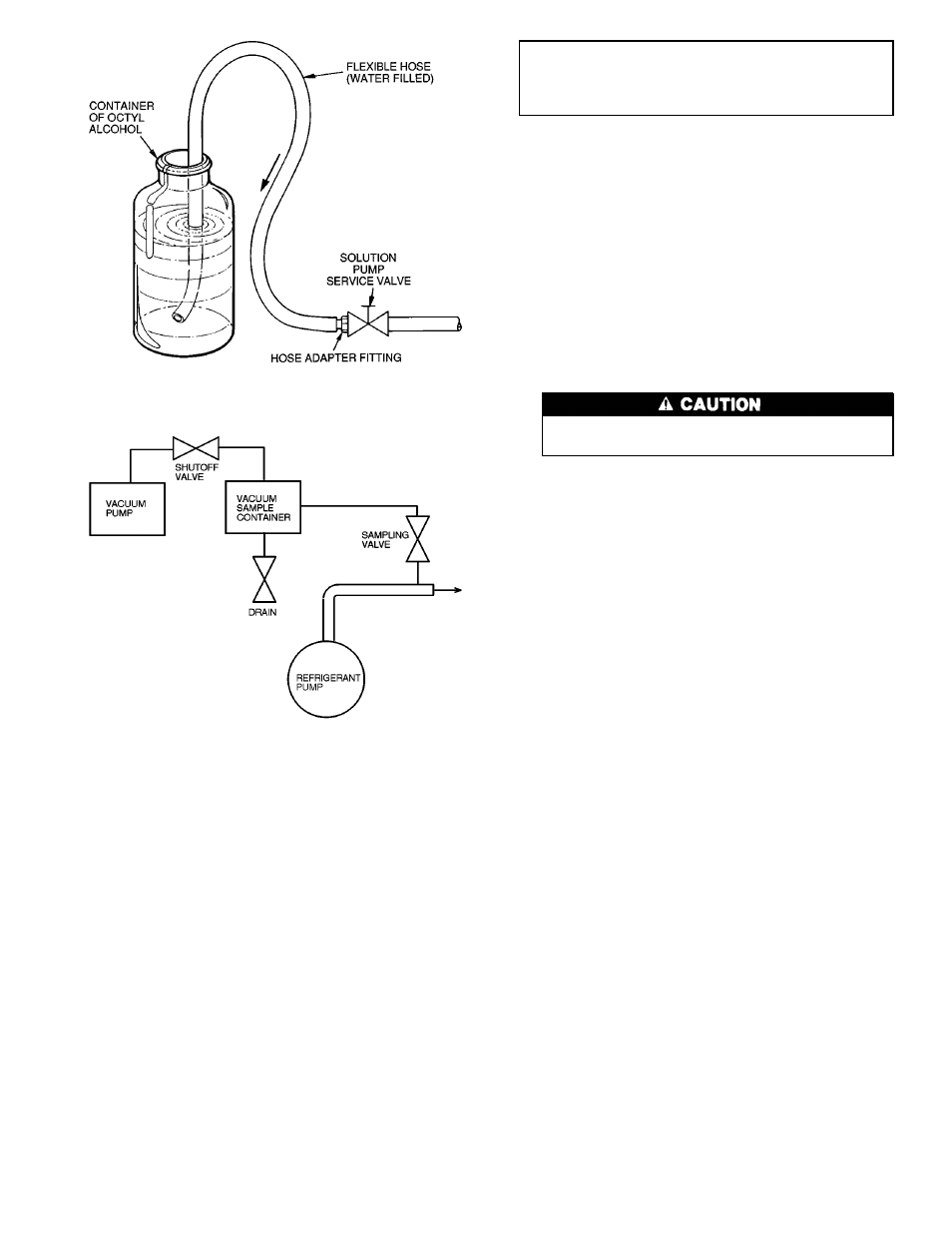
2. Fill a length of flexible tubing with water and connect
one end to the high-temperature generator drain valve (see
Fig. 35). Insert the other end in a container of octyl al-
cohol. Open the service valve to allow alcohol to be drawn
into the machine. Close valve before air can be drawn
into the hose.
Removing Lithium Bromide from Refrigerant —
During normal operation, some lithium bromide may be car-
ried over into the refrigerant. Lithium bromide in the refrig-
erant is automatically transferred back to the absorber by re-
frigerant overflow valve as needed and by the shutdown dilution
valve. The refrigerant flows through the overflow pipe or di-
lution valve into the solution circuit and separation is made
in the generator in the normal manner.
Lithium bromide can be transferred manually by placing
the dilution switch at MANUAL while the machine is run-
ning and the capacity control valve is open. When the re-
frigerant specific gravity drops below 1.02, return the switch
to AUTO. to close the dilution valve.
Refrigerant Charge Adjustment —
Check the evapo-
rator refrigerant (water) charge after every 6 months of op-
eration. An increase in the amount of water in the machine
indicates tube leakage. Furthermore, the correct refrigerant
charge must be maintained for accurate refrigerant overflow
to prevent solution crystallization.
For charge adjustment, refer to Refrigerant Charge Final
Adjustment, page 40.
Capacity Control Adjustment —
Check the leaving
chilled water temperature. If design temperature is not being
maintained, reset the control set point in the machine control
panel, according to the Automatic Capacity Control expla-
nation in the Machine Controls section, page 31.
If machine still fails to maintain design temperature, refer
to the Troubleshooting sections entitled Problem/Symptom
— Leaving Chilled/Hot Water Temperature Too High, or Too
Low, page 54.
Operating and Limit Controls —
Refer to the vari-
ous control checkout procedures in the Before Initial Start-Up
section, page 32, to verify the correct operation of the ma-
chine operating and limit controls.
Fig. 35 — Adding or Removing Liquids
Fig. 36 — Refrigerant Sampling Technique
49