Carrier 16DF013-050 User Manual
Page 31
Automatic Capacity Control —
The machine auto-
matic capacity control system senses the chilled water or hot
water temperature, compares it to selected cooling or heat-
ing temperature set points, and regulates the burner to adjust
the machine capacity for maintaining the chilled or hot wa-
ter temperature at the set points.
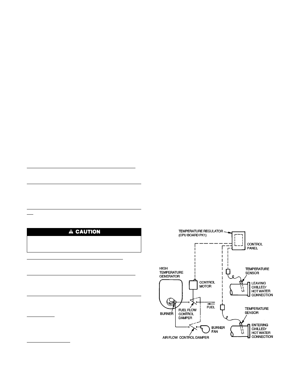
Figure 27 schematically shows the automatic capacity con-
trol system. Temperature sensors are located in both leaving
and entering chilled/hot water piping, the burner is regulated
by modulating the fuel and air, and the system is controlled
by the machine microprocessor.
At full load conditions, the burner will be at or near the
maximum firing rate. As the load decreases, the burner will
be modulated to a reduced firing rate in proportion to the
load. When the heat input required for the load is below the
minimum firing rate, the burner will be cycled off and on.
TEMPERATURE CONTROL SETTINGS — The control point
settings for automatic control of the chilled water and hot
water temperatures are factory preset for typical operating
conditions, but can be reset in 1° C (1.8° F) increments with
the machine adjustment switches.
Cooling and heating operation each require 3 temperature
settings. They include operating temperature settings for the
burner modulating range, limit temperature settings to cycle
the burner off with low load conditions, and limit reset tem-
perature settings for cycling the burner back on at low load
conditions. There are also selections to use either the leav-
ing or entering water temperature sensor, and the capacity
control change signal rate. See Set Point and DIP Switches
section, page 16 for temperature selection instructions.
Chilled water operating temperature (burner modulation) —
SW2 — Factory set at 7 C (44.6 F), adjustable from 5 to
14 C (41 to 57.2 F).
Chilled water low-temperature limit (low load, burner off)
— SW9 (switches 3 and 4) — Factory set at 6 C (42.8 F),
adjustable from 5 to 8 C (41 to 46.4 F). Must be set below
the chilled water operating temperature, typically 1° C
(1.8° F) below.
Chilled water low-temperature limit reset (low load, burner
on) — SW9 (switches 1 and 2) — Factory set at +4° C
(+7.2° F) above operating set point, adjustable from +2 to
+5° C (+3.6 to +9° F).
Never allow the leaving chilled water temperature to fall
below 5 C (41 F). If it does, readjust the temperature set
points upwards.
Hot water operating temperature (burner modulation) — SW10
(switches 1 and 2) plus SW1 — Factory set at 60 C (140 F),
adjustable from 40 to 79 C (104 to 174.2 F).
Hot water high-temperature limit (low load, burner off) —
SW9 (switches 7 and 8) — Factory set at +2° C (+3.6° F)
above the operating set point, adjustable from +1 to
+4° C (+1.8 to +7.2° F).
Hot water high-temperature limit reset (low load, burner on)
— SW9 (switches 5 and 6) — Factory set at -5° C (9° F)
below operating set point, adjustable from -2 to -5° C (-3.6
to -9° F).
Control sensor — SW11 (switch 2) — Selects either the out-
let (leaving) sensor or inlet (entering) sensor for controlling
the chilled water and hot water temperatures. It is factory
selected for outlet temperature, and that setting should be
used for normal applications.
Capacity control speed — SW10 (switches 7 and 8 for speed
1, and switch 6 for speed 2) — This determines the capacity
control response rate to ensure timely adjustment to load changes
without system control cycling. Capacity control speed 1 is
factory selected for open/close signal increments every
60 seconds, adjustable for 30, 60, 120, or 180 second inter-
vals. Capacity control speed 2 is factory selected for open/
close signal increments every 90 seconds, adjustable for 90-
and 180-second intervals. The factory settings should be used
for normal applications.
Example Cooling Temperature Control — With the factory
temperature setting selections listed above, the capacity would
be controlled by the leaving chilled water temperature sen-
sor. The burner would modulate between the maximum and
minimum firing rates to hold the chilled water temperature
at the 7 C (44.6 F) setting.
When a low load requires less than the minimum burner
firing rate, the chilled water temperature will gradually fall
until it reaches the low limit setting of 6 C (42.6 F), and the
burner will be stopped. Then, with the burner off, the chilled
water temperature will gradually rise until it reaches the
+4° C (+7.2° F) reset setting of 11 C (51.8 F), and the burner
will be restarted.
Example Heating Temperature Control — With the factory
temperature setting selections listed above, the capacity would
be controlled by the leaving hot water temperature sensor.
The burner would modulate between the maximum and mini-
mum firing rates to hold the hot water temperature at the
60 C (140 F) setting.
When a low load requires less then the minimum burner
firing rate, the hot water temperature will gradually rise until
it reaches the +2° C (+3.6° F) high limit setting of 62° C
(143.6° F), and the burner will be stopped. Then, with the
burner off, the hot water temperature will gradually fall until
it reaches the -5° C (-9° F) reset setting of 55 C (131 F), and
the burner will be restarted.
CHILLED/HOT WATER TEMPERATURE DISPLAY — The
temperatures being measured by the chilled/hot water sen-
sors can be displayed in °C, along with the temperatures of
the other machine sensors, by the 3-character indicator on
the front of the control panel. This is done by placing DIP
switch 6 on SW11 in the UP position. The leaving chilled or
hot water temperature is displayed by channel 0 (first char-
acter), and the entering water temperature is channel 3. See
Table 7, Digital Temperature Display Codes.
Fig. 27 — Automatic Capacity Controller
31