Carrier 16DF013-050 User Manual
Page 25
Typical Control Sequence — Normal Cooling
Start (Fig. 24)
1. When power is supplied to the chiller control panel and
the machine is not in operation, the status indicator will
display ‘‘000’’.
2. For starting, the machine and burner switches should be
positioned as shown in Table 8, and the manual cooling/
heating valves positioned for cooling (Table 9).
NOTE: The Cool switch selection must be made before
the Start button is depressed.
3. When the Start button is depressed, the microprocessor
will initiate the timed starting and system checks se-
quence. The chilled water pump will be started, if not al-
ready running. After 20 seconds, the pump run interlock(s)
will be checked to verify if the pump is running. If it is,
the status indicator will display ‘‘CPO’’. If not, the se-
quence will be halted until the interlocks show the pump
is running.
4. The capacity controller then will be queried to see if there
is a need for cooling. If not, the sequence will be halted.
If cooling is required, the cooling water pump will be started,
if not already running. After 20 seconds, the pump run
interlock(s) will be checked to verify it is running. If it is,
the start sequence will proceed. If not, the sequence will
be halted until the interlocks show the pump is running.
When the pump is running, the status indicator will dis-
play ‘‘CPP’’.
5. The cooling water temperature will be checked and, if it
is not too low, the cooling tower fan will be started, if not
already running. The status indicator will now display
‘‘CPP’’. At the same time, the solution pump and burner
will be started. The refrigerant pump will be started after
a short time delay. The chiller is now in normal
operation. The control system will continuously monitor
the capacity controller for load requirements, the safety
interlocks for abnormal conditions, and operating limits
for override control when necessary.
Typical Control Sequence — Normal Heating
Start (Fig. 24)
1. When power is supplied to the chiller control panel and
the machine is not in operation, the status indicator will
display ‘‘000’’.
2. For starting, the machine and burner switches should be
positioned as shown in Table 8, and the manual cooling/
heating valves positioned for heating (Table 9).
NOTE: The Heat switch selection must be made before
the Start button is depressed.
3. When the Start button is depressed, the microprocessor
will initiate the timed starting and system checks se-
quence. The hot water pump will be started, if not al-
ready running. After 20 seconds, the pump run interlock(s)
will be checked to verify it is running. If it is, the status
indicator will display ‘‘HPO’’. If not, the sequence will
be halted until the interlocks show the pump is running.
4. The capacity controller then will be queried to see if there
is a need for heating. If not, the sequence will be halted.
If there is, the start sequence will proceed.
5. The solution pump and the burner will be started. The
status indicator will display ‘‘HPO’’. The heater is now
in normal operation. The control system will continu-
ously monitor the capacity controller for load require-
ments, the safety interlocks for abnormal conditions, and
operating limits for override control when necessary.
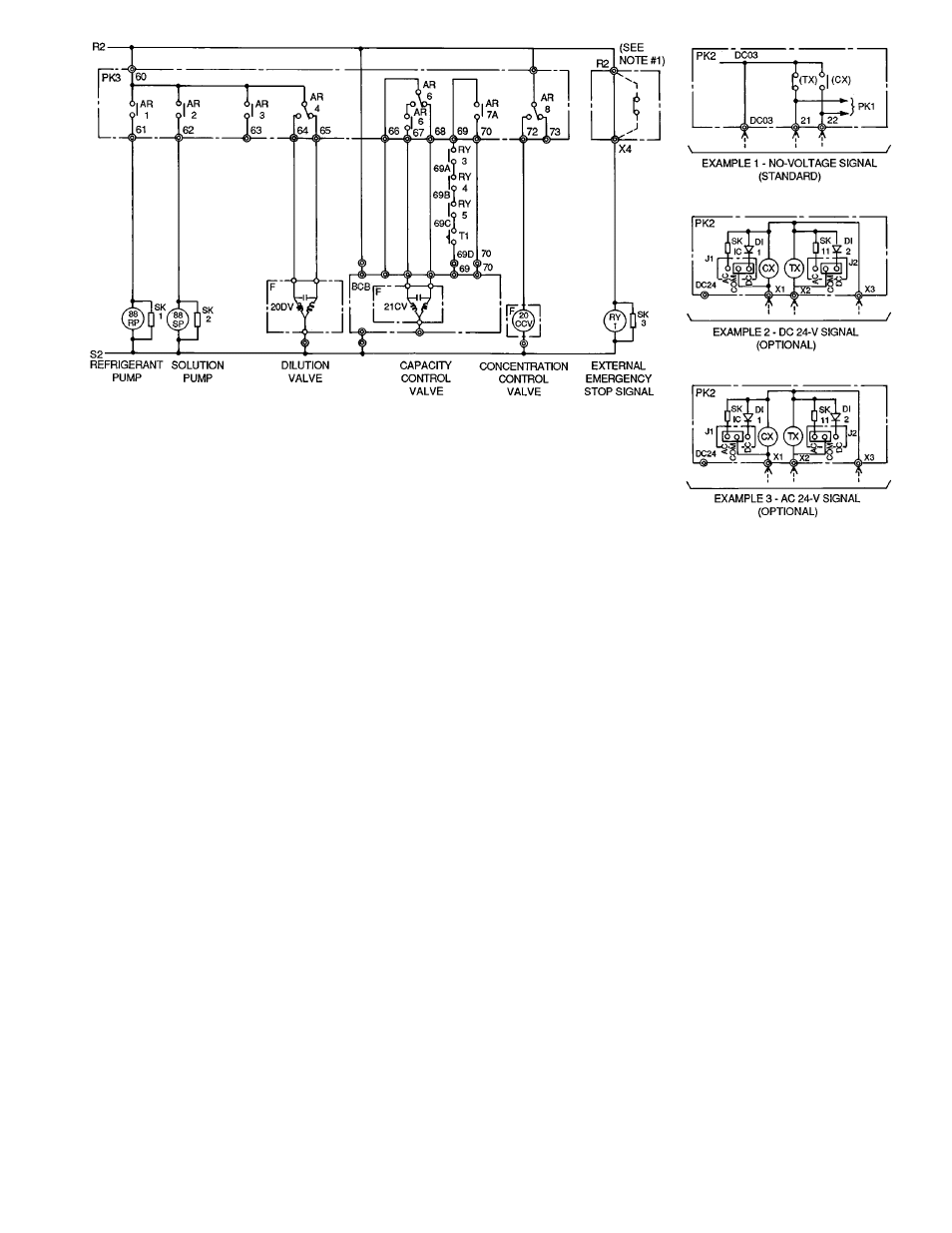
NOTES:
1. When the contacts of external emergency stop signals are con-
nected, remove the jumper wire between terminal R2 and X4 and
connect external contacts to these terminals.
2. BCB — installed in burner control box.
3. F — Positioning motor.
4. PK2 — input terminal module in control panel.
5. PK3 — output terminal module in control panel.
REMOTE OPERATION CIRCUIT
Fig. 23 — PK2 and PK3 Partial Wiring Connections
25