Status indicator sticker, Adjustment switches – Carrier 16DF013-050 User Manual
Page 15
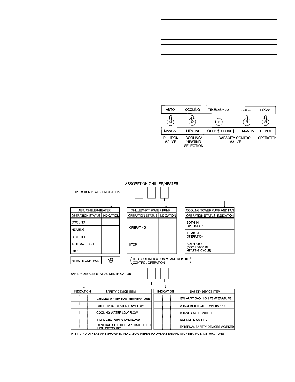
Status Indicator Sticker —
The sticker shown in
Fig. 11 is located on the front of the control panel. It iden-
tifies the basic codes for machine operating status and safety
shutdown, as displayed by the 3-character indicator on the
front of the control panel.
NOTE: See Digital Temperature Display, page 16, and Ad-
justment Switches, below, for switch selections that display
temperatures being measured by the machine sensors as well
as the machine cumulative run time.
Adjustment Switches —
These are located on the cir-
cuit board on the inside panel door.
TOGGLE SWITCHES (Fig. 12) — These are summarized
in Table 6 and discussed in greater detail in various sections
throughout this manual.
Table 6 — Control Panel Toggle Switches
SYMBOL
TOGGLE SWITCH
DESCRIPTION
TS1
On-Off
Direct Current Power Supply
TS2
Auto.-Manual
Dilution Valve
TS3
Cool-Heat
Select Cool/Heat
TS4
Open-Close
Capacity Control Valve
TS5
Auto.-Manual
Capacity Control Valve
TS6
Remote-Local
Operation
NOTES:
1. Time display selection shows the cumulative machine operating time in hours
on the panel door operating status indicator. With the capacity control valve
selection in the AUTO. position, momentarily depressing the switch to OPEN
displays the first 3 digits of the time, and depressing the switch to CLOSE
displays the last 2 digits and decimal. Example:
OPEN position indicates = 012
CLOSE position indicates = 345
Cumulative run time = 01234.5 hours
2. With capacity control valve selection in the MANUAL position, momentarily
depressing the switch to OPEN or CLOSE will move the burner fuel control
valve and air damper proportionally open or closed.
Fig. 11 — Control Panel Status Indicator Sticker
Fig. 12 — Control Panel Toggle Switches
15