Carrier 16DF013-050 User Manual
Page 13
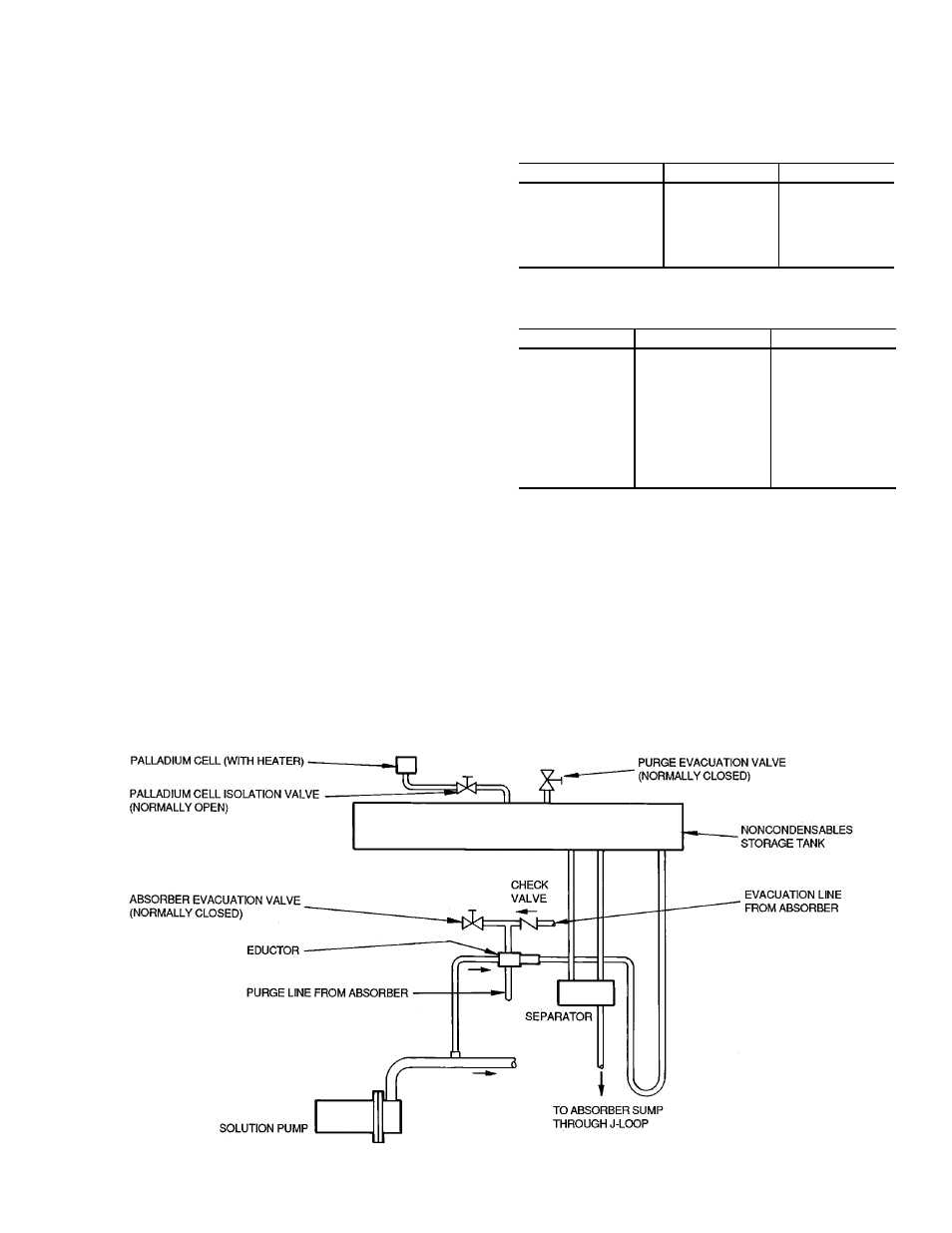
Purge —
The basic components and flow circuits of the
motorless purge are shown in Fig. 9.
The purge system automatically removes noncondens-
ables from the machine and transfers them to a storage cham-
ber where they cannot affect machine operation.
Noncondensables are gases which will not condense at the
normal chiller operating temperatures and pressures (N
2
, O
2
,
H
2
, etc.) and, because they reduce the machine vacuum, they
would also reduce the machine capacity.
Hydrogen (H
2
) gas is liberated within the machine during
normal operation, and its rate of generation is controlled by
the solution inhibitor. The presence of most other gases in
the machine would occur either through a leak (the machine
is under a deep vacuum) or during service activities.
While the machine is operating, any noncondensables ac-
cumulate in the absorber which is the lowest pressure area
of the machine.
For purging, noncondensables are continuously drawn from
the absorber into the lower pressure of an eductor, where
they are entrained in solution flowing from the solution pump.
The mixture then continues on to the purge storage tank. The
noncondensables are released in a separator and the solution
flows back to the absorber by way of the generator overflow
pipe. Typically most of the noncondensable gas is hydrogen,
which is automatically passed out to the atmosphere through
a heated palladium membrane cell.
Any other gas accumulates in the purge storage tank where
it is isolated from the rest of the machine. It is then removed
from the storage tank, when necessary, by a vacuum pump
connected to the tank exhaust valve. If the machine is main-
tained in a leak-tight condition, as it should be, the storage
tank is normally exhausted once or twice a year, during a
normal shutdown period or seasonal changeover. When it is
necessary to remove noncondensables directly from the ma-
chine, such as after service work, a vacuum pump can be
connected to the auxiliary evacuation valve, which is con-
nected directly to the absorber through an isolation check
valve.
Operation Status Indicators —
The 16DF absorp-
tion chiller/heater is equipped with several instruments and
sight glasses for direct observation of its operation in addi-
tion to a digital display of the temperature sensed for ma-
chine control and for codes (Tables 4 and 5).
Table 4 — 16DF Instruments
DESCRIPTION
LOCATION
FUNCTION
High-Temperature
Generator Compound
Gage
Low-Temperature
Generator
Steam Chamber
High-Temperature
Generator
Vessel Pressure
Exhaust Gas
Thermometer
High-Temperature
Generator
Exhaust Stack
Exhaust Gas
Discharge
Temperature
Table 5 — 16DF Sight Glass
DESCRIPTION
LOCATION
FUNCTION
Absorber Sight
Glass
Evaporator Refrigerant
Overflow Pipe
Absorber
Liquid Level
Refrigerant Overflow
High-Temperature
Generator
Sight Glass
High-Temperature
Generator Level
Control Device Box
High-Temperature
Generator
Liquid Level
Combustion
Chamber
Sight Glass
High-Temperature
Generator
Combustion Chamber
Return End
Combustion and
Refractory
Insulation
Status
Burner —
The burner is a packaged, forced-draft type,
with modulating firing rate control. It is supplied with com-
ponents selected for operation with either gas, light oil, or
both fuels, and with appropriate safety and control compo-
nents to comply with specified code, insurance, and juris-
dictional agency requirements.
Specific information is contained in the burner manual ac-
companying each burner.
Fig. 9 — Purge System
13