Carrier 16DF013-050 User Manual
Page 20
LEGEND FOR WIRING DIAGRAMS (Fig. 18 - 23), Pages 20 - 25
3CI
— Three-Character Indicator
20CCV
— Concentration Control Valve Positioner
21CV
— Burner Capacity Control Positioner
20DV
— Dilution Valve
26CA
— Fire Tube High-Temperature Switch
26EH
— Burner Exhaust Gas High-Temperature Switch
26SP
— Solution Pump High Motor Temperature Switch
51BF
— Burner Blower Motor Overload Relay
51RP
— Refrigerant Pump Overload Relay
51SP
— Solution Pump Overload Relay
69CW 1,2 — Chilled Water and Cooling Water Flow Switches
86X
— Burner Safety Auxiliary Relay
88BF
— Burner Blower Motor Starter
88CP
— Cooling Water Pump Starter
88EP
— Chilled/Hot Water Pump Starter
88CT
— Cooling Tower Fan Starter
88RP
— Refrigerant Pump Starter
88SP
— Solution Pump Starter
AR1-8
— Machine Control Relays
BCB
— Burner Control Box
BZ
— Alarm Buzzer
C/H
— Chiller/Heater
CX
— Remote Control Auxiliary Relay*
CN1-10
— Wiring Cable Connectors
ET1,2
— Grounds
F0
— End-Contact Fuse
F1-5
— Enclosed Fuses
G1
— High-Stage Generator
GH
— High-Stage Generator, High-Solution Level Switch
M1-3
— Three-Phase Motors
MCB1,2
— Main Circuit Breakers
MCP
— Machine Control Panel
NF1,2
— Line Noise Filters
PB1
— Start Pushbutton
PB2
— Stop Pushbutton
PK1
— Main Circuit Board
PK2
— Input Terminal Circuit Board
PK3
— Output Terminal Circuit Board
RY1
— External Emergency Stop Auxiliary Relay
RY2-5
— Burner Safety Shutdown Auxiliary Relays
SK1-3
— Surge Suppressors
ST1
— Display Code Identification Sticker
SWR1,2
— Switching Regulators
T1
— Burner Safety Shutdown (‘‘Off’’ Delay Timer)
T3H, T4H — Temperature Sensors
TB
— Terminal Boards
TR1
— Transformer
TR2
— Direct Current Control Circuit Transformer
TR3
— Alternating Current Control Circuit Transformer
TS1
— Direct Current Power Supply (On/Off)
TS2-6
— Operation Switches
TX
— Remote Control Circuit Auxiliary Relay*
Factory Wiring
Field Wiring
Optional Wiring
*CX, TX auxiliary relays for remote operation are optionally installed
signals.
NOTES:
1. BCB — installed in burner control box.
2. F — installed on chiller/heater.
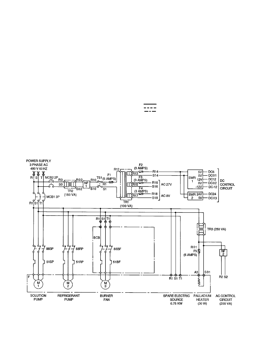
Fig. 18 — Control Panel Power Wiring Schematic
20