Carrier 16DF013-050 User Manual
Page 33
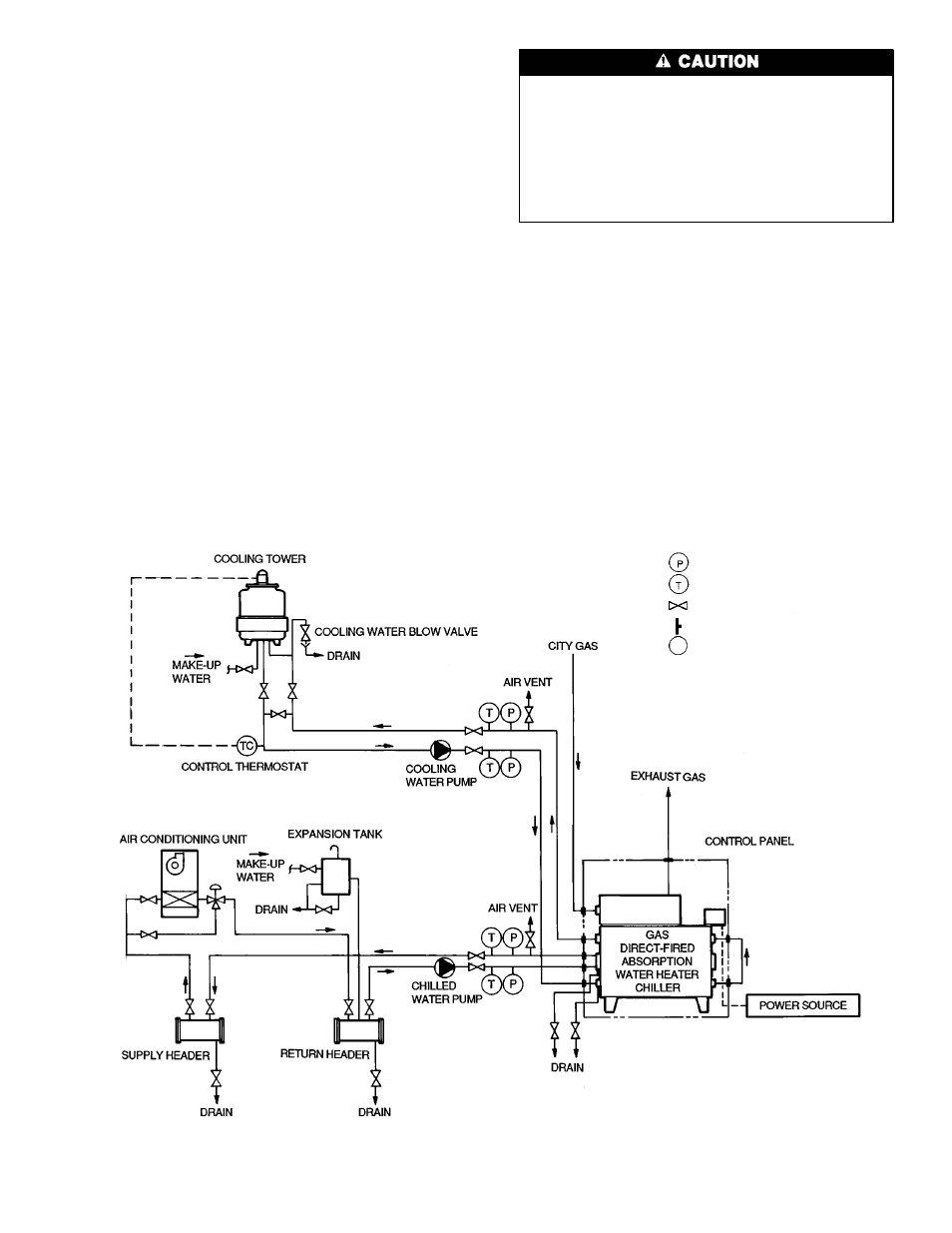
Inspect Field Piping —
Refer to the field piping dia-
grams and inspect the chilled/hot water and cooling water
piping. (See Fig. 28 for typical piping arrangement.)
1. Verify location and flow direction of the water lines as
are specified on the drawings.
2. Check that all water lines are vented and properly sup-
ported to prevent stress on water box covers or nozzles.
3. Make sure all water box drains are installed.
4. Ensure that water flow through the evaporator and con-
denser meet job requirements. Measure the pressure drops
across both cooler and condenser water tube bundles when
the system has been charged with water and the pumps
can be operated.
5. Make sure chilled/hot water temperature sensors are in-
stalled in the leaving and entering chilled/hot water pip-
ing. Also check that appropriate thermometers or temperature
wells and pressure gage taps have been installed in both
entering and leaving sides of the evaporator, absorber, and
condenser water piping.
Inspect Field Wiring —
Refer to the field and ma-
chine wiring diagrams and inspect the wiring for both power
supply and connections to other system equipment (cooling
tower, water supply pumps, auto. start if used, etc.).
Do not connect or disconnect any wiring, and do not
touch any bare wires or wiring terminals unless power
supply disconnects have been locked open and tagged.
Do not apply power to hermetic pumps or attempt to
start the machine until it has been charged with lithium
bromide solution and refrigerant at initial start-up. The
pumps will be severely damaged if rotated without the
full liquid charge. Open disconnects in control panel if
power is to be applied.
1. Examine wiring for conformance to job wiring diagrams
and applicable electrical codes.
2. Check pump and motor nameplates and control panel for
agreement with supply voltage and frequency (hertz).
3. Verify correct overload and fuse sizes for all motors.
4. Check that electrical equipment and controls are properly
grounded in accordance with applicable electrical codes.
5. Make sure customer/contractor has verified proper op-
eration of water pumps, cooling tower fan, and associ-
ated auxiliary equipment. This includes ensuring that motors
are properly lubricated and have correct electrical power
supply and rotation.
NOTE: See manufacturer’s burner manual for fuel line components.
Fig. 28 — Typical Piping and Wiring
Pressure Gage
Thermometer
Valve
Piping Connection
Pump
ᮣ
33