Carrier 16DF013-050 User Manual
Page 48
Machine Evacuation —
Evacuation is required for the
removal of excessive noncondensables from the machine. The
machine must be evacuated after air has entered the machine
during service work, when absorber loss is greater than 5° F
(2.8° C) during operation, or when the machine absolute pres-
sure is greater than 1 in. Hg (25 mm Hg) at shutdown.
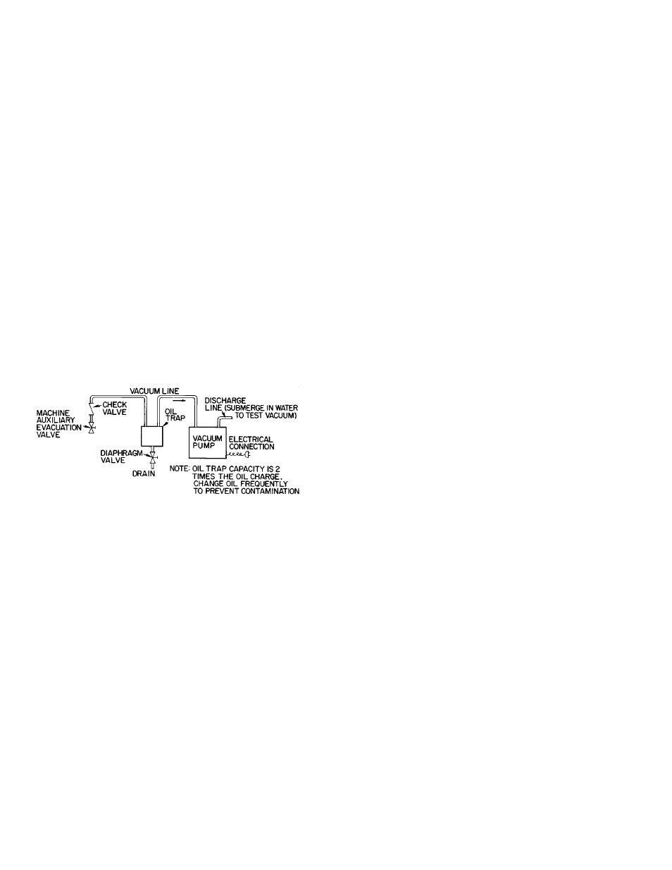
1. Connect an auxiliary evacuation device to the auxiliary
evacuation valve (Fig. 34). Use a line size at least equal
to the connection size on the auxiliary device and keep
the line as short as possible. A check valve must be used
on the suction lines. Be sure all connections are vacuum
tight.
A vacuum pump oil trap can also serve as a cold trap if
it has a center well to hold dry ice or a mixture of salt and
ice. Any water vapor that can contaminate the oil in the
vacuum pump is condensed and removed by the cold trap.
The cold trap thus reduces the time required for evacu-
ation and eliminates the need for frequent replacement of
the pump oil charge.
2. Start evacuation device. After one minute open auxiliary
evacuation valve. If the machine is not operating, reduce
machine absolute pressure to the pressure equivalent of
the saturation temperature of the refrigerant. If the ma-
chine is operating, evacuate until absorber loss is 5° F
(2.8° C) or less.
3. Close auxiliary evacuation valve and turn off auxiliary
evacuation device.
4. Machine evacuation can remove octyl alcohol. Check a
solution sample for the presence of octyl alcohol and add
if necessary (see Adding Octyl Alcohol, page 49).
Purge Exhaust Procedure —
See Machine Descrip-
tion, pages 3 - 13, for an explanation of the purge operation,
component identification, and Fig. 9 illustration.
Hydrogen gas, which is generated normally in the ma-
chine, is exhausted to the atmosphere from the purge storage
tank through the heated palladium membrane cell. This is
done automatically and continuously during machine
operation.
Other noncondensables are stored in the purge storage tank
and are removed manually with a vacuum pump (not part of
the machine) through the purge exhaust valve. Typically this
is done only once or twice a year, while the machine is shut
down at the end of the cooling and heating seasons. How-
ever, an excessive absorber loss (see Absorber Loss Deter-
mination, page 46), may indicate the need for more frequent
purging as a result of an air leak, palladium cell not func-
tioning, or solution inhibitor depletion.
Follow the appropriate steps under Machine Evacuation,
this page, to remove stored noncondensbles through the purge
exhaust valve with a vacuum pump and oil trap.
Solution or Refrigerant Sampling —
(See precau-
tions pertaining to handling lithium bromide solution as de-
scribed in Initial Start-Up, Solution and Refrigerant Charg-
ing, page 37).
Take solution or refrigerant samples form the pump serv-
ice valve while the pump is operating.
Before taking a sample for analysis or absorber loss de-
termination, be sure machine is operating with steady load
and that there has not been any refrigerant overflow within
10 minutes prior to sampling.
Attach a hose adapter to the pump service valve. Do not
use copper or brass fittings when taking samples for analy-
sis; copper oxide can form and contaminate samples.
The solution pump normally discharges at above atmo-
spheric pressure, but the refrigerant pump discharges at
a vacuum, so the respective sampling procedures are
different.
SOLUTION SAMPLE
1. Fill a length of flexible tubing with water and connect
one end to the hose adapter. Place the free end in a con-
tainer of water. Be sure end is submerged (Fig. 35).
2. Open valve slightly. When container water level rises, wait
several seconds to purge the water from the tube. Then
remove tube end from water and fill sample container.
3. Turn off service valve and remove hose and adapter.
REFRIGERANT SAMPLE (Fig. 36)
1. Connect a clean, empty vacuum container to the pump
service valve with a length of flexible hose.
2. Connect a vacuum pump to the vacuum container with a
flexible hose and isolation valve.
3. Pull a deep vacuum on the container and close the iso-
lation valve.
4. Open the service valve slightly to drain refrigerant sample
into the container.
5. Turn off service valve, remove hose and adpater, and dis-
connect vacuum pump.
Fig. 34 — Machine Evacuation Device
48