Carrier 16DF013-050 User Manual
Page 27
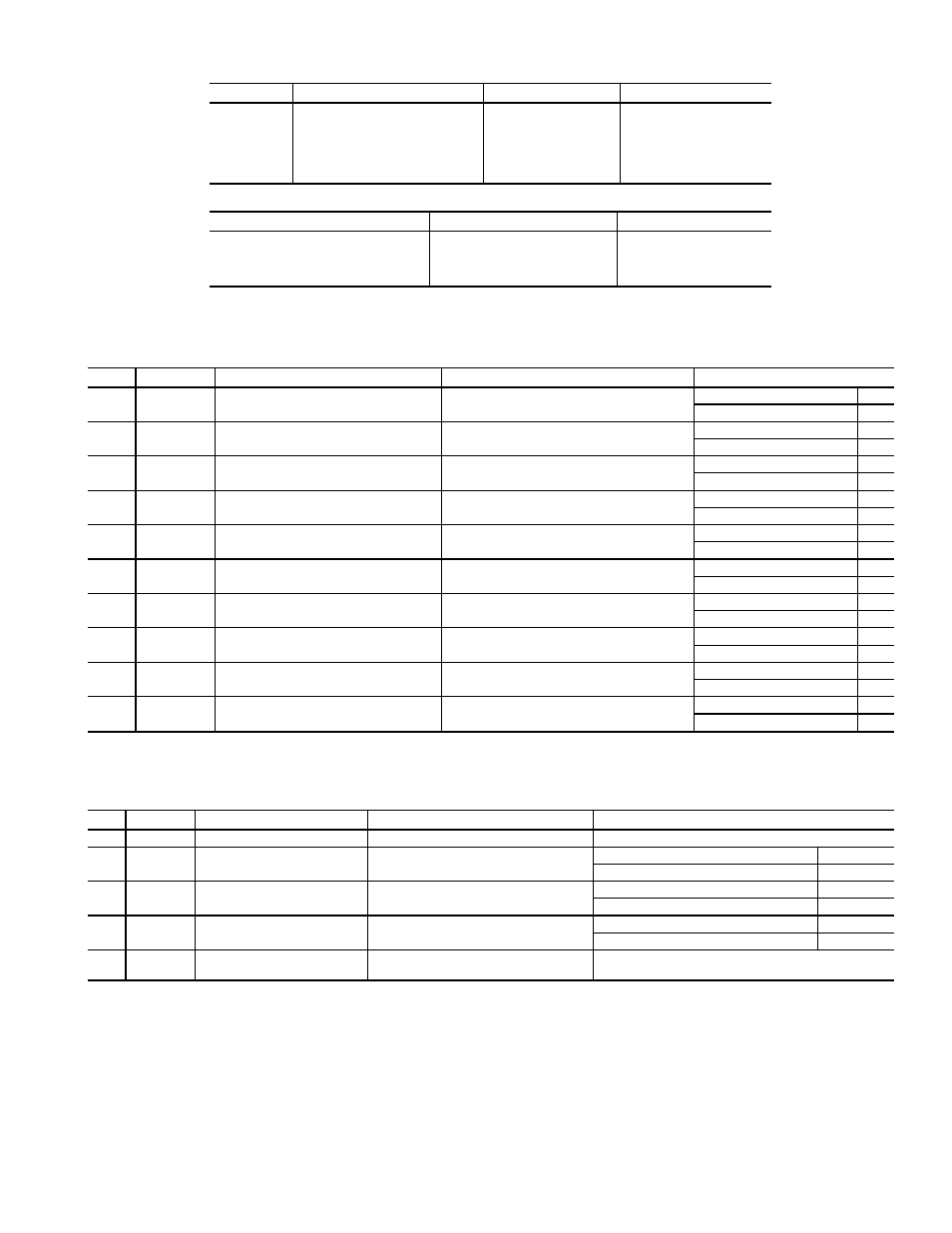
Table 8 — Switch Positions for Start-Up
MACHINE CONTROL PANEL
SYMBOL
DESCRIPTION
TOGGLE SWITCH
SETTING
TS1
Direct Current Power Supply
On-Off
ON
TS2
Dilution Valve
Auto.-Manual
AUTO.
TS3
Select Cool/Heat
Cool-Heat
COOL OR HEAT
TS4
Capacity Control Valve
Open-Close
(NEUTRAL)
TS5
Capacity Control Valve
Auto.-Manual
AUTO.
TS6
Operation
Remote-Local
REMOTE OR LOCAL
BURNER CONTROL PANEL
DESCRIPTION
TOGGLE SWITCH
SETTING
Burner Control
On-Off
ON
Firing Rate Selector
Auto.-Manual
AUTO.
Firing Position
Open-Stop-Close
STOP
Fuel Selection (if used)
Gas-Oil
GAS OR OIL
Table 9 — 16DF Valves
MANUAL VALVES
NO.
SYMBOL
DESCRIPTION
LOCATION
OPERATION*
1
A
Heating/Cooling Vapor Valves
High-Temperature Vapor Discharge Pipe
Cooling Cycle
C
Heating Cycle
O
2
B
Heating/Cooling Liquid Valve
Underside Refrigerant Tank
Cooling Cycle
C
Heating Cycle
O
3
C
Heat Exchanger Bypass
Solution Heat Exchanger
Normal Operation
C
Service
O
4
D
Palladium Cell Isolation
Palladium Cell Connection Pipe
Normal Operation
O
Service
C
5
E
Purge Storage Tank Evacuation
Purge Tank
Normal Operation
C
Purge Discharge
O
6
F
Auxiliary Evacuation
Purge Pipe
Normal Operation
C
Machine Evacuation
O
7
G
Vacuum/Pressure Gage Connection
Absorber Shell
Normal Operation
C
Vacuum/Pressure Check
O
8
H
Solution Pump Service
Solution Pump Discharge
Normal Operation
C
Service
O
9
J
Refrigerant Pump Service
Refrigerant Pump Discharge
Normal Operation
C
Service
O
10
K
High-Stage Generator Service
Underside High Temperature Generator
Normal Operation
C
Service
O
*Valve positions — O = FULLY OPEN; C = FULLY CLOSED.
AUTOMATIC VALVES
NO.
SYMBOL
DESCRIPTION
LOCATION
OPERATION*
1
21CV
Capacity Control Valves
Burner Fuel Line and Air Damper
Proportional between high fire and low fire
2
—
Fuel Valves
Burner Fuel Line
Burner On
O
Burner Off
C
3
20DC
Dilution Valve
Evaporator Refrigerant Overflow Pipe
Dilution Cycle
O
Normal Operation
C
4
20CCV
Concentration Control Valve
Condenser Refrigerant Return Pipe
Concentration Control Cycle
O
Normal Operation
C
5
LCD
Solution Flow Control
Weak Solution Pipe
Reduces flow for low loads and low cooling water
temperature.
*Valve positions — O = FULLY OPEN; C = FULLY CLOSED.
27