Machine controls, General, Start-stop system – Carrier 16DF013-050 User Manual
Page 14: Machine control panel
MACHINE CONTROLS
This machine uses a microprocessor control system. Do
not short or jumper between terminations on printed cir-
cuit boards. Control or board failure may result. Also,
when performing welding, wiring, or an insulation re-
sistance test on the machine, disconnect wiring to the
CPU (Control Processing Unit) board to avoid risk of
voltage damage to the board components.
Be aware of electrostatic discharge (static electricity)
when handling or making contact with the printed cir-
cuit boards. Always touch a grounded chassis part to
dissipate body electrostatic charge before working in-
side the control center.
Use extreme care when handling tools near boards
and when connecting or disconnecting terminal plugs.
Circuit boards can easily be damaged. Always hold boards
by edges and avoid touching components and pin con-
nections. Always store and transport replacement or de-
fective boards in anti-static bags.
General —
The 16DF machine uses a microprocessor-
based control center which monitors and controls all opera-
tions of the machine. It also has a separate burner control
center, under direction of the machine control center, to pro-
vide burner sequence control and combustion supervision.
The integrated control system matches the cooling and heat-
ing capacities of the machine to the respective cooling and
heating loads, while providing state-of-the-art machine
protection.
The system controls the machine output temperatures within
the set point deadband by sensing the leaving chilled and hot
water temperatures and regulating the burner heat input ac-
cordingly. Machine protection is provided by continuously
monitoring critical conditions and performing control over-
rides or safety shutdowns, if required.
Start-Stop System —
The type of start-stop system is
selected by the customer. The most commonly used systems
are described below. Review the descriptions and determine
which system applies to your job.
SEMIAUTOMATIC START-STOP — In this basic system,
auxiliary equipment is wired into the machine control cir-
cuit and machine is started and stopped manually with the
machine Start and Stop switches. Two variations are used:
With Pilot Relays — The coils for the chilled/hot water and
condensing water pump starters (or other auxiliary equip-
ment) are wired into the machine control circuit so that the
auxiliary equipment operates whenever machine operates. The
starter contacts and starter overloads remain in the external
pump circuits. The pump flow switch(es) and auxiliary starter
circuits are also wired into the machine control circuit and
must be closed for the machine to operate.
With Manual Auxiliaries — With this system, the auxiliaries
must be started manually and independently from the ma-
chine start, and they must be operating before the machine
can start. As with the pilot relay system above, the flow
switch(es) and auxiliary starter contacts are in the machine
control circuit and must be closed for the machine to
operate.
FULL AUTOMATIC START-STOP — This system is ba-
sically the same as the semiautomatic system with pilot re-
lays described above. Machine and auxiliary start and stop,
however are controlled by a field-supplied thermostat, timer,
or other automatic device when the TS6 Local/Remote switch
is in the REMOTE position, and the machine Start switch
has been depressed.
Machine Control Panel —
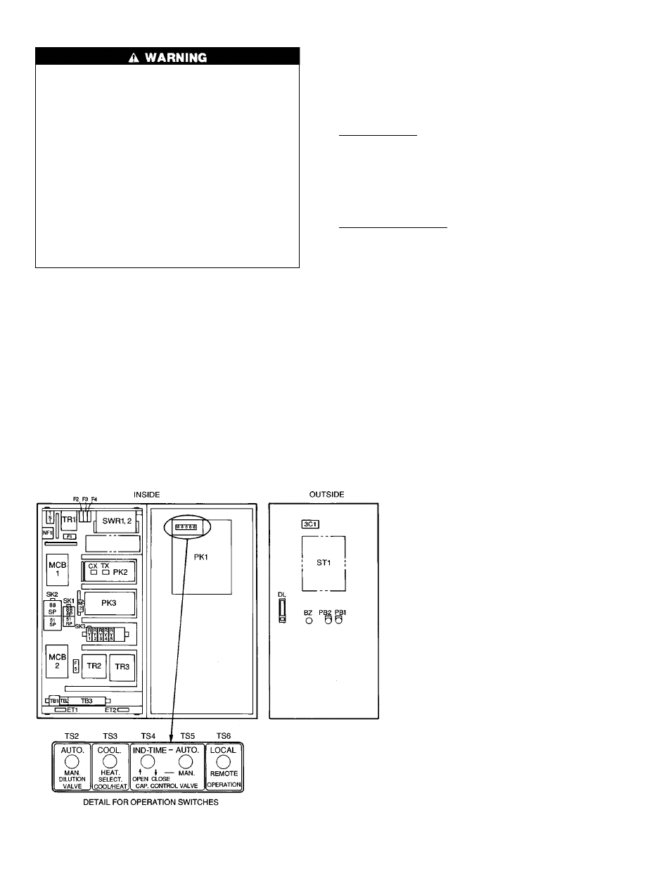
The 16DF standard con-
trol panel is shown in Fig. 10.
Fig. 10 — Control Panel
LEGEND
3CI
— Three-Character Indicator
51RP
— Refrigerant Pump Overcurrent Relay
51SP
— Solution Pump Overcurrent Relay
88RP
— Refrigerant Pump Electromagnetic
Contactor
88SP
— Solution Pump Electromagnetic
Contactor
BZ
— Alarm Buzzer
CX
— Remote Control Auxiliary Relay*
DL
— Door Latch
ET1,2
— Grounds
F0
— End-Contact Fuse
F1-5
— Enclosed Fuses
MCB1,2 — Main Circuit Breakers
NF1,2
— Line Noise Filters
PB1
— Start Pushbutton Switch
PB2
— Stop Pushbutton Switch
PK1
— Central Processing Unit (CPU) Board
PK2
— Input Terminal Module
PK3
— Output Terminal Module
RY1
— External Emergency Stop Auxiliary Relay
RY2-5
— Burner Safety Shutdown Auxiliary Relays
SK1-3
— Surge Suppressors
ST1
— Display Code Identification Sticker
(see also Fig. 11)
SWR1,2 — Switching Regulators
T1
— Burner Safety Shutdown (‘‘Off’’ Delay Timer)
TB1-3
— Terminal Boards
TR1
— Transformer
TR2
— Direct Current Control Circuit
Transformer
TR3
— Alternating Current Control Circuit Transformer
TS2-6
— Operation Switches
TS1
— Direct Current Power Supply (On/Off)
TX
— Remote Control Circuit Auxiliary Relay*
*CX,TX auxiliary relays for remote operation are
optionally installed signals.
14