Edge Lighting TruLine 1.6A, 24VDC - Plaster-In LED system User Manual
Page 3
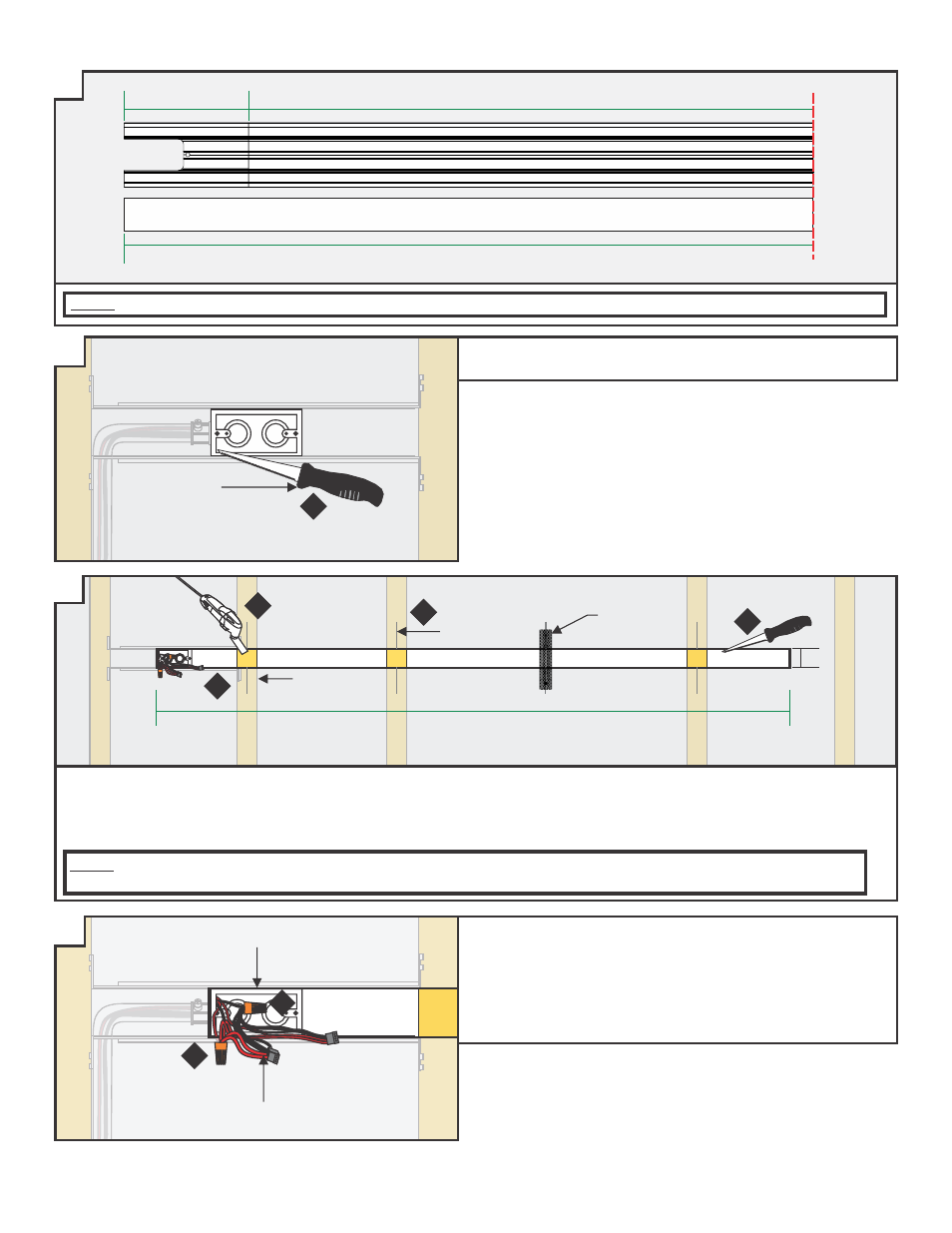
5: Mark the area where the channel will be located on the drywall using the junction box opening as a guide (MIN 2.25").
6: Cut out the marked area using a "Dremel Multi-Max" or a 6" Fixed Jab Saw.
8: Mark the location of the studs to the drywall for future reference.
E
3
NOTE: To install channel in a wall without standard-spaced studs, install perforated mounting straps every 32" behind drywall
and secure using two drywall screws. Mark the location of any mounting straps to the drywall.
MARKING
STUD
NOTE: If cutting channel to length, ensure that the lens is also cut to match the total length of the installation.
C
STARTER
SECTION
CHANNEL
SECTION
CUT LENS LENGTH TO TOTAL LENGTH
MOUNTING
STRAP
D
NOTE: If cutting channel to length, ensure that the lens is also cut to match the total length of the installation.
6" FIXED
JAB SAW
4: Cut a section of drywall where the junction box will be located
using a 6" fixed jab saw or other appropriate tool.
WIDTH OF
INSTALLATION
2.25"
F
9: Connect the red power supply (24VDC+) wires to each red
power wire with a wire nut inside the junction box.
10: Connect the black power supply (24VDC-) wires to each black
power wire with a wire nut inside the junction box.
11: Place the wire nut connections inside junction box.
JUNCTION BOX
POWER
WIRE
9
10
5
6
6
8
4