Z2 z3 – Edge Lighting TruLine .5A, 24VDC - Plaster-In LED System User Manual
Page 9
9
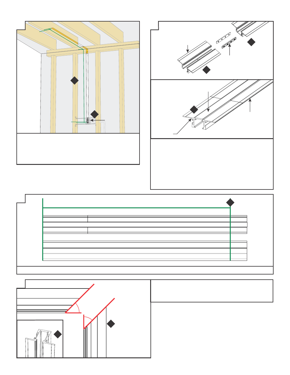
1: Install junction box and low-voltage power.
2: Measure and mark installation length, allowing for 0.75"
extra space at junction box for power end cap and 1.0" inch
at the end of the installation for the take-up box. Cut
out marked areas using appropriate tools.
1
WALL
CEILING
JUNCTION
BOX
0.75"
1.0"
DESIRED LIT LENGTH
DESIRED LIT LENGTH
3: Insert the joiner bars halfway into the channel trap door
frame. Tighten the two #4-40 set screws on each joiner bar
with a 0.05" Allen wrench.
4: Slide the other section of channel onto the joining bars and
tighten the remaining #4-40 set screws with a 0.05" Allen
wrench.
5: Snap the lens into all channel sections BEFORE cutting to
length. This ensures a proper fit after installation.
4
CHANNEL
JOINER
BAR
TRAP DOOR
FRAME
TRAP DOOR
FRAME
LENS
6: Mark the desired lit length on the assembled channel and lens lengths.
45°
45°
7: Miter cut each section of assembled channel and lens to
match the corner angle. In a 90° inside corner installation
as shown, each channel section is cut at a 45° angle to
form a complete corner.
SIDE VIEW
Z5
7
7
ANGLE VIEW
Z2
Z3
2
3
5
6
MARK DESIRED LIT LENGTH
ASSEMBLED LENS AND CHANNEL w/TRAP DOOR FRAME
ADDITIONAL CHANNEL AND LENS SECTIONS AS REQUIRED
Z4